|
|
|
PDF LT8330 Data sheet ( Hoja de datos )
| Número de pieza | LT8330 | |
| Descripción | Low IQ Boost/SEPIC/Inverting Converter | |
| Fabricantes | Linear | |
| Logotipo | ||
Hay una vista previa y un enlace de descarga de LT8330 (archivo pdf) en la parte inferior de esta página. Total 24 Páginas | ||
|
No Preview Available !
Features
nn 3V to 40V Input Voltage Range
nn Ultralow Quiescent Current and Low Ripple Burst
Mode® Operation: IQ = 6µA
nn 1A, 60V Power Switch
nn Positive or Negative Output Voltage Programming
with a Single Feedback Pin
nn Fixed 2MHz Switching Frequency
nn Accurate 1.6V EN/UVLO Pin Threshold
nn Internal Compensation and Soft-Start
nn Low Profile (1mm) ThinSOT™ Package
nn Low Profile (0.75mm) 8-Lead (3mm × 2mm) DFN
Package
Applications
nn Industrial and Automotive
nn Telecom
nn Medical Diagnostic Equipment
nn Portable Electronics
LT8330
Low IQ Boost/SEPIC/
Inverting Converter
with 1A, 60V Switch
Description
The LT®8330 is a current mode DC/DC converter capable
of generating either positive or negative output voltages
using a single feedback pin. It can be configured as a
boost, SEPIC or inverting converter consuming as low as
6µA of quiescent current. Low ripple Burst Mode opera-
tion maintains high efficiency down to very low output
currents while keeping the output ripple below 15mV in
a typical application. The internally compensated current
mode architecture results in stable operation over a wide
range of input and output voltages. Integrated soft-start
and frequency foldback functions are included to control
inductor current during start-up. The 2MHz operation
combined with small package options, enables low cost,
area efficient solutions.
L, LT, LTC, LTM, Linear Technology, the Linear logo and Burst Mode are registered trademarks
and ThinSOT is a trademark of Linear Technology Corporation. All other trademarks are the
property of their respective owners.
Typical Application
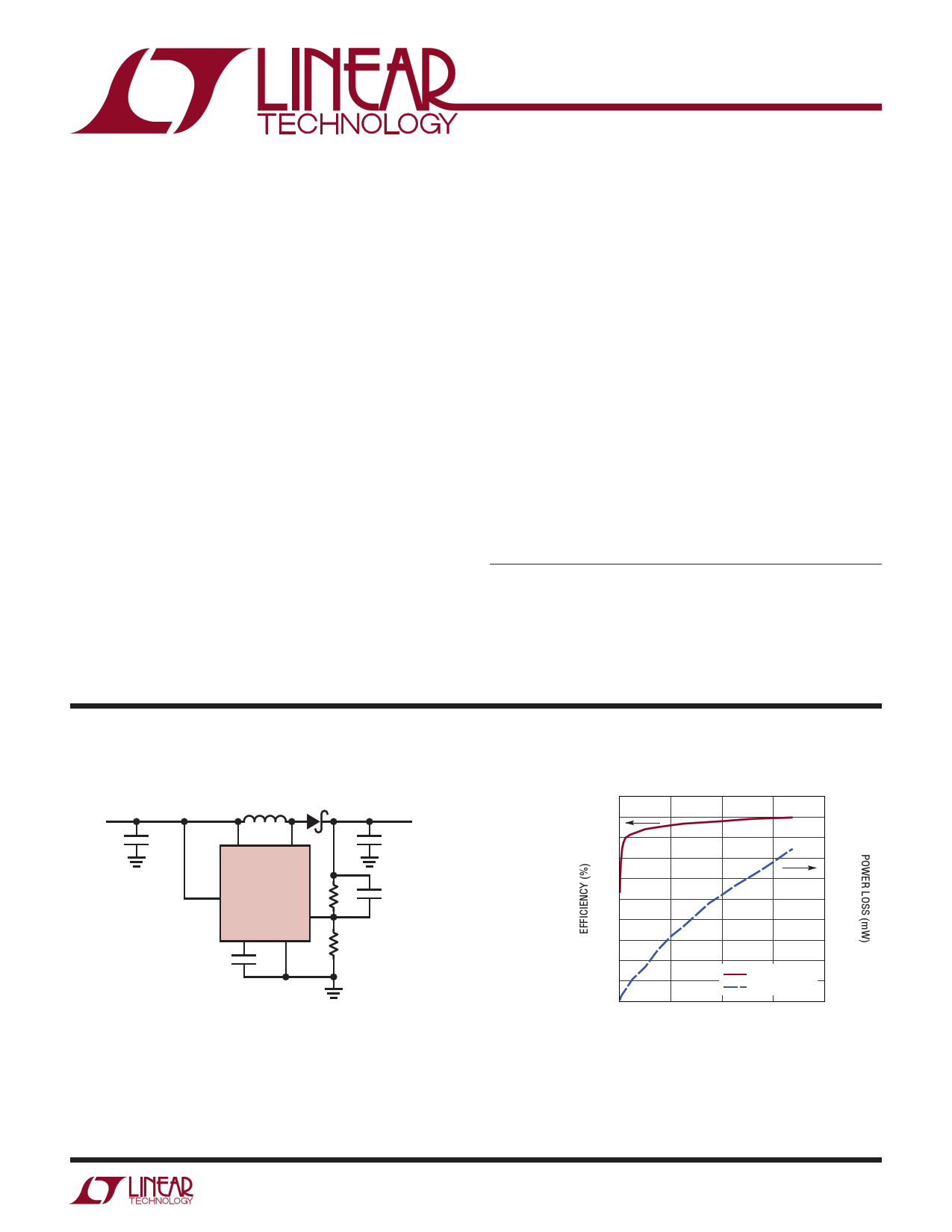
48V Boost Converter
VIN
12V
4.7µF
6.8µH
VIN SW
VOUT
48V
4.7µF 135mA
LT8330
EN/UVLO
1M 4.7pF
FBX
INTVCC GND
1µF
34.8k
100
90
80
70
60
50
40
30
20
10
0
0
Efficiency and Power Loss
1000
900
800
700
600
500
400
300
200
EFFICIENCY
POWER LOSS
100
0
40 80 120 160
LOAD CURRENT (mA)
8330 TA01b
For more information www.linear.com/LT8330
8330fa
1
1 page 
Typical Performance Characteristics
LT8330
VSIwNitPcihninCgu)rrvesnTte(mSlpeeerpatMuroede, Not
10.00 VIN = 12V
8.75
7.50
6.25
5.00
3.75
2.50
1.25
0
–50 –25 0 25 50 75 100 125 150 175
JUNCTION TEMPERATURE (°C)
8330 G10
Switching Waveforms
(in CCM)
SVIwNitPcihninCgu)rrvesnTte(mAcpteivreatMuroede, Not
1000 VIN = 12V
950
900
850
800
750
700
650
600
–50 –25 0 25 50 75 100 125 150 175
JUNCTION TEMPERATURE (°C)
8330 G11
Switching Waveforms
(in DCM/Light Burst Mode)
Burst Frequency vs Load Current
2.5
FRONT PAGE APPLICATION
2.0 VIN = 12V
VOUT = 48V
1.5
1.0
0.5
0
0 10 20 30 40 50
LOAD CURRENT (mA)
8330 G12
Switching Waveforms
(in Deep Burst Mode)
IL
500mA/DIV
IL
500mA/DIV
IL
500mA/DIV
VSW
20V/DIV
VSW
20V/DIV
VSW
20V/DIV
1µs/DIV
FRONT PAGE APPLICATION
VIN = 12V, VOUT = 48V, ILOAD = 135mA
8330 G13
1µs/DIV
FRONT PAGE APPLICATION
VIN = 12V, VOUT = 48V, ILOAD = 20mA
8330 G14
1µs/DIV
FRONT PAGE APPLICATION
VIN = 12V, VOUT = 48V, ILOAD = 2mA
8330 G15
VOUT Transient Response: Load
Current Transients from 67.5mA to
135mA to 67.5mA
FRONT PAGE APPLICATION
IL
100mA/DIV
VOUT
500mV/DIV
VIN = 12V
VOUT = 48V
100µs/DIV
8330 G16
VOUT Transient Response: Load
Current Transients from 5mA to
135mA to 5mA
FRONT PAGE APPLICATION
IL
100mA/DIV
VIN = 12V
VOUT = 48V
VOUT
500mV/DIV
100µs/DIV
8330 G17
For more information www.linear.com/LT8330
8330fa
5
5 Page 
LT8330
Applications Information
Switching Frequency and Inductor Selection
The LT8330 switches at 2MHz, allowing small value induc-
tors to be used. 0.68µH to 10µH will usually suffice. Choose
an inductor that can handle at least 1.4A without saturating,
and ensure that the inductor has a low DCR (copper-wire
resistance) to minimize I2R power losses. Note that in
some applications, the current handling requirements of
the inductor can be lower, such as in the SEPIC topology
where each inductor only carries one-half of the total
switch current. For better efficiency, use similar valued
inductors with a larger volume. Many different sizes and
shapes are available from various manufacturers. Choose
a core material that has low losses at 2MHz, such as a
ferrite core. The final value chosen for the inductor should
not allow peak inductor currents to exceed 1A in steady
state at maximum load. Due to tolerances, be sure to ac-
count for minimum possible inductance value, switching
frequency and converter efficiency.
Table 1. Inductor Manufacturers
Sumida
(847) 956-0666
TDK (847) 803-6100
Murata
(714) 852-2001
Coilcraft
(847) 639-6400
Würth
(605) 886-4385
www.sumida.com
www.tdk.com
www.murata.com
www.coilcraft.com
www.we-online.com
Input Capacitor
Bypass the input of the LT8330 circuit with a ceramic ca-
pacitor of X7R or X5R type placed as close as possible to
the VIN and GND pins. Y5V types have poor performance
over temperature and applied voltage, and should not be
used. A 4.7µF to 10µF ceramic capacitor is adequate to
bypass the LT8330 and will easily handle the ripple cur-
rent. If the input power source has high impedance, or
there is significant inductance due to long wires or cables,
additional bulk capacitance may be necessary. This can
be provided with a low performance electrolytic capacitor.
A precaution regarding the ceramic input capacitor con-
cerns the maximum input voltage rating of the LT8330.
A ceramic input capacitor combined with trace or cable
inductance forms a high quality (under damped) tank cir-
cuit. If the LT8330 circuit is plugged into a live supply, the
input voltage can ring to twice its nominal value, possibly
exceeding the LT8330’s voltage rating. This situation is
easily avoided (see Application Note 88).
Output Capacitor and Output Ripple
Low ESR (equivalent series resistance) capacitors should
be used at the output to minimize the output ripple voltage.
Multilayer ceramic capacitors are an excellent choice, as
they are small and have extremely low ESR. Use X5R or
X7R types. This choice will provide low output ripple and
good transient response. A 4.7µF to 15µF output capacitor
is sufficient for most applications, but systems with very
low output currents may need only a 1µF or 2.2µF output
capacitor. Solid tantalum or OS-CON capacitor can be
used, but they will occupy more board area than a ceramic
and will have a higher ESR. Always use a capacitor with a
sufficient voltage rating.
Compensation
The LT8330 is internally compensated. The decision to
use either low ESR (ceramic) capacitors or the higher
ESR (tantalum or OS-CON) capacitors, for the output
capacitor, can affect the stability of the overall system.
The ESR of any capacitor, along with the capacitance
itself, contributes a zero to the system. For the tantalum
and OS-CON capacitors, this zero is located at a lower
frequency due to the higher value of the ESR, while the
zero of a ceramic capacitor is at a much higher frequency
and can generally be ignored.
A phase lead zero can be intentionally introduced by placing
a capacitor in parallel with the resistor between VOUT and
FBX. By choosing the appropriate values for the resistor and
capacitor, the zero frequency can be designed to improve
the phase margin of the overall converter. The typical target
value for the zero frequency is between 30kHz to 60kHz.
A practical approach to compensation is to start with one
of the circuits in this data sheet that is similar to your ap-
plication. Optimize performance by adjusting the output
capacitor and/or the feed forward capacitor (connected
across the feedback resistor from output to FBX pin).
For more information www.linear.com/LT8330
8330fa
11
11 Page | ||
| Páginas | Total 24 Páginas | |
| PDF Descargar | [ Datasheet LT8330.PDF ] | |
Hoja de datos destacado
| Número de pieza | Descripción | Fabricantes |
| LT8330 | Low IQ Boost/SEPIC/Inverting Converter | Linear |
| LT8331-41 | STANDARD LED LAMP | Ledtech |
| LT8331-41 | STANDARD LED LAMP | Ledtech |
| Número de pieza | Descripción | Fabricantes |
| SLA6805M | High Voltage 3 phase Motor Driver IC. |
Sanken |
| SDC1742 | 12- and 14-Bit Hybrid Synchro / Resolver-to-Digital Converters. |
Analog Devices |
|
DataSheet.es es una pagina web que funciona como un repositorio de manuales o hoja de datos de muchos de los productos más populares, |
| DataSheet.es | 2020 | Privacy Policy | Contacto | Buscar |