|
|
|
PDF MCP3302 Data sheet ( Hoja de datos )
| Número de pieza | MCP3302 | |
| Descripción | Low Power A/D Converter | |
| Fabricantes | Microchip | |
| Logotipo | ||
Hay una vista previa y un enlace de descarga de MCP3302 (archivo pdf) en la parte inferior de esta página. Total 30 Páginas | ||
|
No Preview Available !
MCP3302/04
13-Bit Differential Input, Low Power A/D Converter
with SPI Serial Interface
Features
• Full Differential Inputs
• 2 Differential or 4 Single-ended inputs (MCP3302)
• 4 Differential or 8 Single-ended Inputs (MCP3304)
• ±1 LSB maximum DNL
• ±1 LSB maximum INL (MCP3302/04-B)
• ±2 LSB maximum INL (MCP3302/04-C)
• Single supply operation: 4.5V to 5.5V
• 100 ksps sampling rate with 5V supply voltage
• 50 nA typical standby current, 1 µA maximum
• 450 µA maximum active current at 5V
• Industrial Temperature Range: -40°C to +85°C
• 14 and 16-pin PDIP, SOIC, and TSSOP packages
• Mixed Signal PICtail™ Demo Board (P/N:
MXSIGDM) compatible
Applications
• Remote Sensors
• Battery-operated Systems
• Transducer Interface
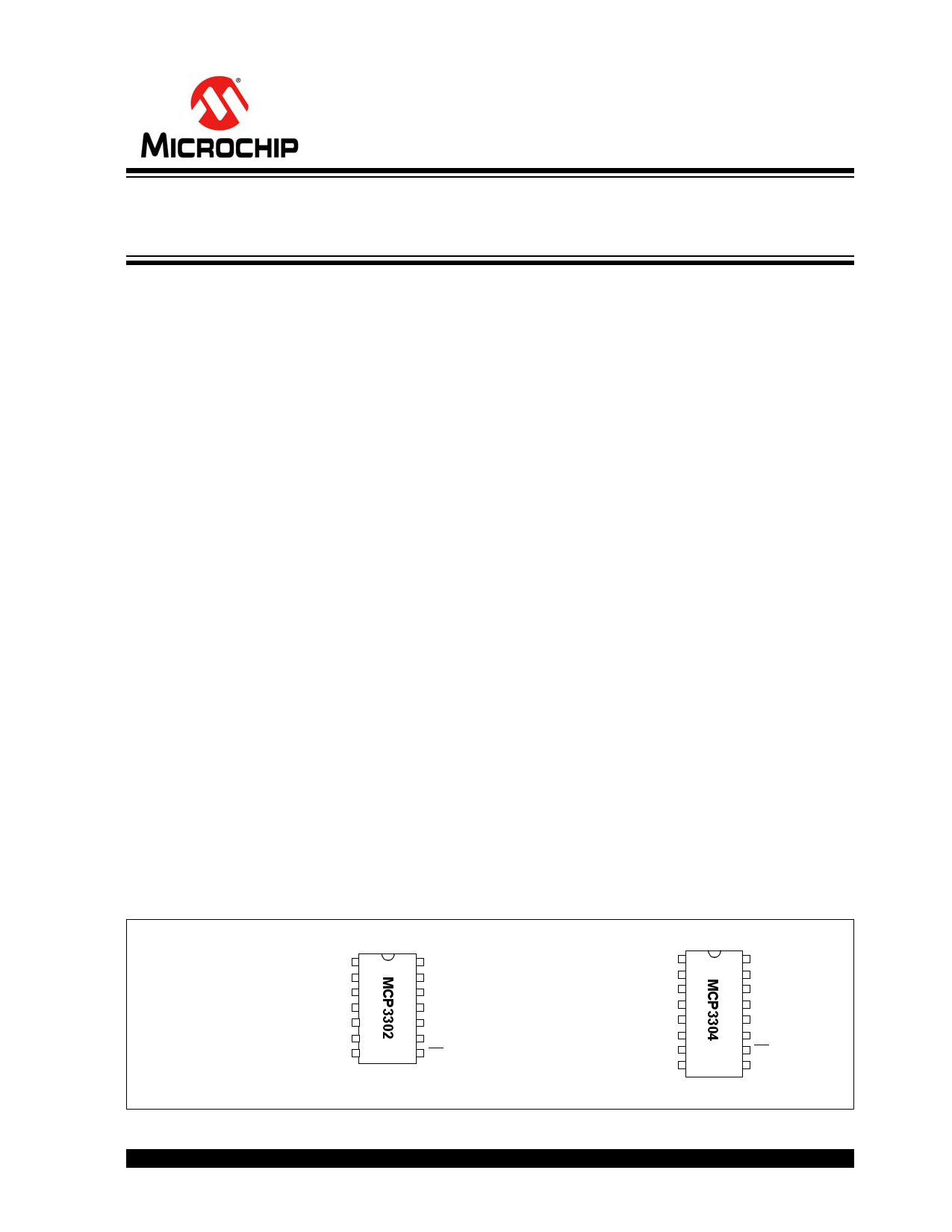
Package Types
PDIP, SOIC, TSSOP
CH0
CH1
CH2
CH3
NC
NC
DGND
1
2
3
4
5
6
7
14 VDD
13 VREF
12 AGND
11 CLK
10 DOUT
9 DIN
8 CS/SHDN
General Description
The MCP3302/04 13-bit A/D converter features full
differential inputs and low-power consumption in a
small package that is ideal for battery-powered
systems and remote data acquisition applications.
The MCP3302 is user-programmable to provide two
differential input pairs or four single-ended inputs.
The MCP3304 is also user-programmable to configure
into four differential input pairs or eight single-ended
inputs.
Incorporating a successive approximation architecture
with on-board sample and hold circuitry, these 13-bit
A/D converters are specified to have ±1 LSB
Differential Nonlinearity (DNL); ±1 LSB Integral
Nonlinearity (INL) for B-grade and ±2 LSB for C-grade
devices. The industry-standard SPI serial interface
enables 13-bit A/D converter capability to be added to
any PIC® microcontroller.
The MCP3302/04 devices feature low current design
that permits operation with typical standby and active
currents of only 50 nA and 300 µA, respectively. The
device is capable of conversion rates of up to 100 ksps
with tested specifications over a 4.5V to 5.5V supply
range. The reference voltage can be varied from
400 mV to 5V, yielding input-referred resolution
between 98 µV and 1.22 mV.
The MCP3302 is available in 14-pin PDIP, 150 mil
SOIC and TSSOP packages. The MCP3304 is
available in 16-pin PDIP and 150 mil SOIC packages.
The full differential inputs of these devices enable a
wide variety of signals to be used in applications such
as remote data acquisition, portable instrumentation,
and battery-operated applications.
PDIP, SOIC
CH0
CH1
CH2
CH3
CH4
CH5
CH6
CH7
1
2
3
4
5
6
7
8
16 VDD
15 VREF
14 AGND
13 CLK
12 DOUT
11 DIN
10 CS/SHDN
9 DGND
2011 Microchip Technology Inc.
DS21697F-page 1
1 page 
MCP3302/04
ELECTRICAL SPECIFICATIONS (CONTINUED)
Electrical Characteristics: Unless otherwise noted, all parameters apply at VDD = 5V, VSS = 0V, and VREF = 5V. Full differential
input configuration (Figure 1-5) with fixed common mode voltage of 2.5V. All parameters apply over temperature with
TA = -40°C to +85°C (Note 7). Conversion speed (FSAMPLE) is 100 ksps with FCLK = 21*FSAMPLE
Parameter
Symbol
Min Typ
Max Units
Conditions
Power Requirements:
Operating Voltage
VDD
4.5 —
5.5
V Note 9
Operating Current
IDD
— 300
450
µA VDD, VREF = 5V, DOUT unloaded
— 200
—
µA VDD, VREF = 2.7V, DOUT unloaded
Standby Current
IDDS
— 0.05
1
µA CS = VDD = 5.0V
Note
1:
2:
3:
4:
5:
6:
7:
8:
9:
This specification is established by characterization and not 100% tested.
See characterization graphs that relate converter performance to VREF level.
VIN = 0.1V to 4.9V @ 1 kHz.
VDD =5V DC ±500 mVP-P @ 1 kHz, see test circuit Figure 1-4.
Maximum clock frequency specification must be met.
VREF = 400 mV, VIN = 0.1V to 4.9V @ 1 kHz.
TSSOP devices are only specified at 25°C and +85°C.
For slow sample rates, see Section 5.2 “Driving the Analog Input” for limitations on clock frequency.
4.5V - 5.5V is the supply voltage range for specified performance.
TEMPERATURE CHARACTERISTICS
Electrical Specifications: Unless otherwise indicated, VDD = +2.7V to +5.5V, VSS = GND.
Parameters
Sym
Min Typ Max Units
Temperature Ranges
Specified Temperature Range
Operating Temperature Range
Storage Temperature Range
Thermal Package Resistances
Thermal Resistance, 14L-PDIP
Thermal Resistance, 14L-SOIC
Thermal Resistance, 14L-TSSOP
Thermal Resistance, 16L-PDIP
Thermal Resistance, 16L-SOIC
TA -40 — +125 °C
TA -40 — +125 °C
TA -65 — +150 °C
JA — 70 — °C/W
JA — 95.3 — °C/W
JA — 100 — °C/W
JA — 70 — °C/W
JA — 86.1 — °C/W
Conditions
TCSH
CS
CLK
DIN
DOUT
TSUCS
TSU THD
MSB IN
THI TLO
TEN
TDO
T
Null Bit
Sign BIT
TF
LSB
TDIS
FIGURE 1-1:
Timing Parameters.
2011 Microchip Technology Inc.
DS21697F-page 5
5 Page 
MCP3302/04
Note: Unless otherwise indicated, VDD = VREF = 5V, Full differential input configuration, VSS = 0V, FSAMPLE = 100 ksps,
FCLK = 21*FSAMPLE, TA = +25°C.
120
100
80
60
40
20
0
2 2.5 3 3.5 4 4.5 5 5.5 6
VDD (V)
FIGURE 2-25:
IREF vs. VDD.
80
70
60
50
40
30
20
10
0
2 2.5 3 3.5 4 4.5 5 5.5 6
VDD (V)
FIGURE 2-28:
IDDS vs. VDD.
120
100
80
60
40
20
0
0 50 100 150 200
Sample Rate (ksps)
FIGURE 2-26:
IREF vs. Sample Rate.
100
10
1
0.1
0.01
0.001
-50
-25
FIGURE 2-29:
0 25 50
Temperature (°C)
75 100
IDDS vs. Temperature.
93
92
91
90
89
88
87
86
-50
0
FIGURE 2-27:
50
Temperature (°C)
100
IREF vs. Temperature.
150
4
3.5
3
2.5
2
1.5
1
0.5
0
-0.5
-1
0123456
VREF (V)
FIGURE 2-30:
Negative Gain Error vs.
Reference Voltage.
2011 Microchip Technology Inc.
DS21697F-page 11
11 Page | ||
| Páginas | Total 30 Páginas | |
| PDF Descargar | [ Datasheet MCP3302.PDF ] | |
Hoja de datos destacado
| Número de pieza | Descripción | Fabricantes |
| MCP3301 | Matched Microchannel Plate Set | ETC |
| MCP3301 | Low Power A/D Converter | Microchip |
| MCP3302 | Low Power A/D Converter | Microchip |
| MCP3304 | Low Power A/D Converter | Microchip |
| Número de pieza | Descripción | Fabricantes |
| SLA6805M | High Voltage 3 phase Motor Driver IC. |
Sanken |
| SDC1742 | 12- and 14-Bit Hybrid Synchro / Resolver-to-Digital Converters. |
Analog Devices |
|
DataSheet.es es una pagina web que funciona como un repositorio de manuales o hoja de datos de muchos de los productos más populares, |
| DataSheet.es | 2020 | Privacy Policy | Contacto | Buscar |