|
|
|
PDF SGM2100 Data sheet ( Hoja de datos )
| Número de pieza | SGM2100 | |
| Descripción | DC-DC Power Management Unit | |
| Fabricantes | Shengbang Microelectronics | |
| Logotipo | ||
Hay una vista previa y un enlace de descarga de SGM2100 (archivo pdf) en la parte inferior de esta página. Total 30 Páginas | ||
|
No Preview Available !
SGM2100
Seven-Channel, High Efficiency,
DC-DC Power Management Unit
GENERAL DESCRIPTION
The SGM2100 is a single chip power management unit for a
wide range of portable applications. It incorporates three
synchronous switching regulators and four switching regulator
controllers in a space saving thin QFN package. High efficiency,
compact size and flexible configuration make SGM2100 the
ideal power supply solution for two AA cells or single Li-ion
battery powered equipments.
Synchronous switching regulators, SU, SD, & MAIN, provide
the core powers for CPU, DSP and I/O. Switching regulator
controllers, AUX1, AUX2, AUX3 and AUX4, coupled with
external MOSFETs provide versatile auxiliary powers for image
sensor, LCD panel bias, LED backlight, stepping motor, or
memory module.
All channels operate at the same programmable constant
switching frequency, ranging from 100kHz to 1MHz. Each
channel, with built-in digital soft-start, can be individually
selected, and programmed to the desired output voltage with
two external resistors. Power OK, short-circuit flag and thermal
protection features provide the system status and extra level of
fault protection.
FEATURES
● 2A, Step-Up Synchronous Switching Regulator with
1.1V Start-Up Voltage, 90% Efficiency
● 1A, Step-Down Synchronous Switching Regulator,
90% Efficiency
● 1A, Pin Selectable Step-Up or Step-Down, Synchronous
Switching Regulator, 90% Efficiency
● Step-Up Switching Regulator Controller, with Power OK
Indicator
● Transformerless Inverting Switching Regulator Controller
● Constant Current Step-Up Switching Regulator Controller,
LED Driver, with Output Open Protection
● Pin Selectable Step-Up or Step-Down Switching Regulator
Controller, with Power OK Indicator
● Operates from 100kHz to 1MHz Switching Frequency
● Individual Enable, Digital Soft-Start and Overload Protection
● 1μA Quiescent Current in Shutdown Mode
● Available in TQFN-7×7-48L Package
APPLICATIONS
Digital still Cameras, Camcorders
Smart Mobile Phones, PDAs
Portable GPS Equipments
Handheld Multi-Media Equipments
The SGM2100 is available in TQFN-7×7-48L package and is
rated over the -40°C to +85°C temperature range.
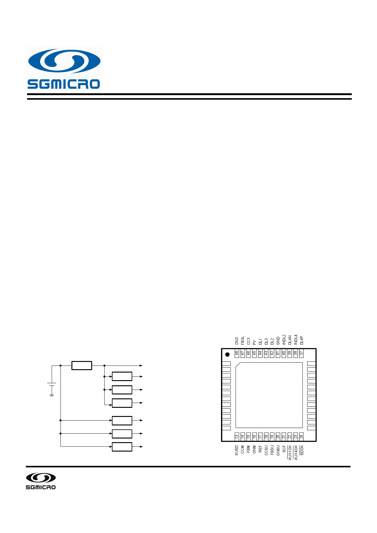
PIN CONFIGURATION (TOP VIEW)
TYPICAL APPLICATION IN
DIGITAL CAMERAS
SU 5V, System Power
2AA/Li-ion
1.5V~4.2V
SD
MAIN
1.8V, DSP
3.3V, I/O
AUX2
-8V, CCD Bias, LCD Bias
AUX1
AUX3
AUX4
15V, LCD Bias
30V, LED Backlight
2.5V, Memory
FB3H
SUSD4
ON4
CC1
FB1
ON1
PGSD
LXSD
PVSD
ONSD
FBSD
CCSD
1
2
3
4
5
6
7
8
9
10
11
12
GND
36 FB2
35 FB4
34 CC2
33 CC4
32 ON2
31 PVM
30 LXM
29 PGM
28 PVSU
27 LXSU
26 PGSU
25 OSC
SG Micro Corp
www.sg-micro.com
REV. A. 2
1 page 
SGM2100
PIN DESCRIPTION
Seven-Channel, High Efficiency,
DC-DC Power Management Unit
PIN NAME
FUNCTION
AUX2 Controller Feedback Input. This pin is high impedance in shutdown.
36 FB2 Option1 AUX2 as a Step-Up: FB2 feedback threshold is 0.8V.
Option2 AUX2 as an inverter: FB2 feedback threshold is 0.8V.
37
DL4P
AUX4 Controller Gate-Drive Output. DL4P drives between INDL4 and GND. The PMIC configures
DL4P to drive a PMOS. DL4P is driven high in shutdown, overload and thermal limit.
Voltage Input of AUX4 Controller Gate-Drive. The voltage at INDL4 sets the high gate-drive voltage.
38 INDL4 PMIC connect INDL4 to the external PMOS source terminal to ensure the PMOS is completely off
when DL4P swing high.
39
DL4N
AUX4 controller Gate-Drive Output. DL4N drives between INDL4 and GND. The PMIC configures
DL4N to drive an NMOS. DL4N is driven high in shutdown, overload and thermal limit.
Voltage input of AUX2 Controller Gate-Drive. The voltage at INDL2 sets the high gate-drive voltage.
40 INDL2 PMIC connect INDL2 to the external PMOS source terminal to ensure the PMOS is completely off
when DL2 swing high.
41 GND Analog Ground. Connect all PGxx_ pins to GND with short wide traces as close to the IC as possible.
AUX2 Controller Gate-Drive Output. DL2 drives between INDL2 and GND. The Option1 configures
DL2 to drive an NMOS in a Boost configuration. AUX2 is driven low in shutdown, overload and
42 DL2 thermal limit.
AUX2 Controller Gate-Drive Output. DL2 drives between INDL2 and GND. The PMIC configures DL2
to drive a PMOS in an Inverter configuration. AUX2 is driven low in shutdown, overload and thermal
limit.
AUX3 Controller Gate-Drive Output. Connect to the gate of an NMOS. DL3 drives between PVSU and
43 DL3 GND and supplies up to 500mA. This pin is actively driven to GND in shutdown, overload, and
thermal limit.
AUX1 Controller Gate-Drive Output. Connect to the gate of an NMOS. DL1 drives between PVSU and
44 DL1 GND and supplies up to 500mA. This pin is actively driven to GND in shutdown, overload, and
thermal limit.
45 PV IC Power Input. Connect PVSU and PV together.
AUX3 Controller Compensation Node. Connect a series resistor-capacitor from this pin to GND to
46 CC3 compensate the control loop of the converter. This pin is actively driven to GND in shutdown,
overload, and thermal limit.
AUX3 Controller Current-Feedback Input. Connect a resistor from FB3L to GND to set LED current in
47 FB3L LED boost-drive circuits. The feedback threshold is 0.2V. Connecting this pin to GND if just use the
FB3H feedback. This pin is high impedance in shutdown.
AUX3 Controller ON/OFF Input. Logic high = ON; however, turn-on is locked out until 1024 OSC
48 ON3 cycles after the step-up has reached regulation. This pin has an internal 475kΩ pull-down resistance
to GND.
SG Micro Corp
www.sg-micro.com
5
5 Page 
SGM2100
Seven-Channel, High Efficiency,
DC-DC Power Management Unit
TYPICAL PERFORMANCE CHARACTERISTICS
Step-Up Efficiency vs. Load Current
100
VIN = 3.8V
80
60
40
20
0
1
VSU = 5V
10 100
Load Current (mA)
1000
AUX1 Efficiency vs. Load Current
100
VIN = 3.8V
80
60
40
20
0
1
VOUT_AUX 1 = 5V
10
Load Current (mA)
100
Main(Step-Down) Efficiency vs. Load Current
100
VIN = 3.8V
80
60
40
20
0
1
VM = 3.3V
10 100
Output Current (mA)
1000
Step-Down Efficiency vs. Load Current
100
VIN = 3.8V
80
60
40
20
0
1
SD = 1.8V
SD Input
Connected
to BATT
10 100
Load Current (mA)
1000
AUX1 Efficiency vs. Load Current
100
VIN = 3.8V
80
60
40
20
0
1
VOUT_AUX1 = 15V
10
Load Current (mA)
100
Main (Step-Up) Efficiency vs.Load Current
100
VIN = 3V
80
60
40
20
0
1
VM = 3.3V
VSU = 5V
10 100
Output Current (mA)
1000
SG Micro Corp
www.sg-micro.com
11
11 Page | ||
| Páginas | Total 30 Páginas | |
| PDF Descargar | [ Datasheet SGM2100.PDF ] | |
Hoja de datos destacado
| Número de pieza | Descripción | Fabricantes |
| SGM2100 | DC-DC Power Management Unit | Shengbang Microelectronics |
| SGM2101 | DC-DC Power Management Unit | Shengbang Microelectronics |
| Número de pieza | Descripción | Fabricantes |
| SLA6805M | High Voltage 3 phase Motor Driver IC. |
Sanken |
| SDC1742 | 12- and 14-Bit Hybrid Synchro / Resolver-to-Digital Converters. |
Analog Devices |
|
DataSheet.es es una pagina web que funciona como un repositorio de manuales o hoja de datos de muchos de los productos más populares, |
| DataSheet.es | 2020 | Privacy Policy | Contacto | Buscar |