|
|
|
PDF RT8463 Data sheet ( Hoja de datos )
| Número de pieza | RT8463 | |
| Descripción | High Voltage Multi-Topology LED Driver | |
| Fabricantes | Richtek | |
| Logotipo | ||
Hay una vista previa y un enlace de descarga de RT8463 (archivo pdf) en la parte inferior de esta página. Total 16 Páginas | ||
|
No Preview Available !
®
RT8463
High Voltage Multi-Topology LED Driver
General Description
The RT8463 is a current mode PWM regulator for LED
driving applications. With a 2A power switch, wide input
voltage (4.5V to 50V) and output voltage (up to 50V)
ranges, the RT8463 can operate in any of the three
common topologies : Buck, Boost or Buck-Boost.
With 470kHz operating frequency, the size of the external
PWM inductor and input/output capacitors can be
minimized. High efficiency is achieved by a 100mV current
sensing control.
Brightness dimming can be controlled from either analog
or PWM signal. A unique built-in clamping comparator
and filtering resistor allow easy low noise analog dimming
conversion from PWM signal with only one external
capacitor.
The RT8463 is available in the TSSOP-14 (Exposed pad)
and WDFN-12L 3x3 packages.
Ordering Information
RT8463
Package Type
CP : TSSOP-14 (Exposed Pad)
QW : WDFN-12L 3x3 (W-Type)
(Exposed Pad-Option 1)
Lead Plating System
G : Green (Halogen Free and Pb Free)
Note :
Richtek products are :
RoHS compliant and compatible with the current require-
ments of IPC/JEDEC J-STD-020.
Suitable for use in SnPb or Pb-free soldering processes.
Features
High Voltage : VIN Up to 50V, VOUT Up to 50V
Buck, Boost or Buck-Boost Operation
Built-In 2A Power Switch
Current Mode PWM Control
470kHz Fixed Switching Frequency
Easy Dimming : Analog, PWM Digital or PWM
Converting to Analog with One External Capacitor
Adjustable Soft-Start to Avoid Inrush Current
Adjustable Over Voltage Protection to Limit Output
Voltage
Thermal Shutdown
Under Voltage Lockout
RoHS Compliant and Halogen Free
Applications
GPS, Portable DVD Backlight
Desk Lights and Room Lighting
Industrial Display Backlight
Marking Information
RT8463GCP
RT8463GCP : Product Number
RT8463
GCPYMDNN
YMDNN : Date Code
RT8463GQW
98=YM
DNN
98 = : Product Code
YMDNN : Date Code
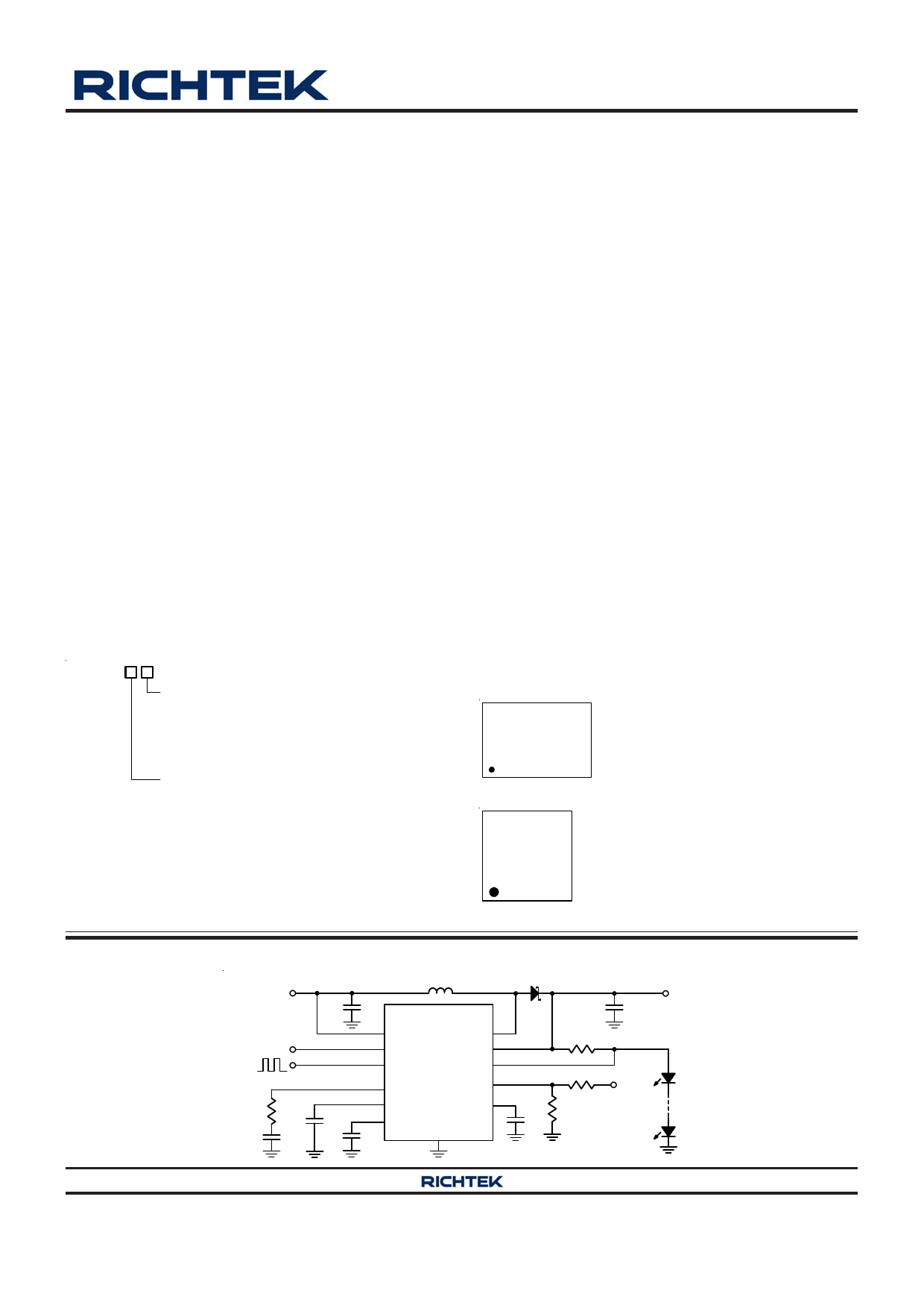
Simplified Application Circuit
L
VIN
C1
RT8463
VCC
SW
5V EN ISP
PWM
Dimming Control
DCTL
VC
ISN
OVP
R1 C3
SS
ACTL
CREG
C2 C4 GND
D1
R2
R3
R4
C5
VOUT
C6
VOUT
Copyright ©2014 Richtek Technology Corporation. All rights reserved.
DS8463-01 August 2014
is a registered trademark of Richtek Technology Corporation.
www.richtek.com
1
1 page 
RT8463
Parameter
Symbol
Input Current
IISP
Input Current
IISN
Output Current
IVC
VC Threshold for PWM Switch Off
Test Conditions
VISP = 24V
VISN = 24V
2V > VC > 0.2V
Min Typ Max Unit
-- 200 --
A
-- 20 -- A
-- 10 --
A
-- 0.2 --
V
LED Dimming
Analog Dimming ACTL Pin Input
Current
IACTL
0 VACTL 3V, DCTL Floating -- -- 2 A
LED Current On Threshold at
ACTL
LED Current Off Threshold at
ACTL
VACTL_ON (VISP VISN) = 100mV
VACTL_OFF
-- 1.2 1.33 V
-- 0.2 0.25 V
DCTL Input Current
IDCTL
0.3V VDCTL 5V
-- 0.5 2 A
DCTL Input
Voltage
Logic-High
Logic-Low
VDCTL_H
VDCTL_L
2 -- --
V
-- -- 0.1
PWM Boost Converter
Switching Frequency
fSW
420 470 520 kHz
Maximum Duty Cycle
DMAX
-- -- 100 %
Minimum On-Time (Note 6)
-- 150 250 ns
SW RDS(ON)
SW Current Limit
OVP and Soft-Start
OVP Threshold
OVP Input Current
Soft-Start SS Pin Current
Temperature Protection
Thermal Shutdown Temperature
Thermal Shutdown Hysteresis
ILIM_SW
VOVP
IOVP
ISS
TSD
TSD
VOVP 1.5V
VSS 2.5V
-- 0.3 0.5
2 2.5 --
A
1.15 1.2 1.25
V
-- -- 50 nA
-- 5 8 A
-- 150 --
-- 20 --
C
C
Note 1. Stresses beyond those listed “Absolute Maximum Ratings” may cause permanent damage to the device. These are
stress ratings only, and functional operation of the device at these or any other conditions beyond those indicated in
the operational sections of the specifications is not implied. Exposure to absolute maximum rating conditions may
affect device reliability.
Note 2. If connected with a 20kΩ serial resistor, ACTL and DCTL can go up to 40V.
Note 3. θJA is measured at TA = 25°C on a high effective thermal conductivity four-layer test board per JEDEC 51-7. θJC is
measured at the exposed pad of the package.
Note 4. Devices are ESD sensitive. Handling precaution is recommended.
Note 5. The device is not guaranteed to function outside its operating conditions.
Note 6. Guaranteed by design, not subjected to production test.
Copyright ©2014 Richtek Technology Corporation. All rights reserved.
DS8463-01 August 2014
is a registered trademark of Richtek Technology Corporation.
www.richtek.com
5
5 Page 
Application Information
Loop Compensation
The RT8463 has an external compensation pin (VC)
allowing the loop response optimized for specific
application. An external resistor in series with a capacitor
is connected from the VC pin to GND to provide a pole
and a zero for proper loop compensation. The
recommended compensation resistance and capacitance
for the RT8463 are 10kΩ and 3.3nF.
Soft-Start
The soft-start can be achieved by connecting a capacitor
from the SS pin to GND. The built-in soft-start circuit
reduces the start-up current spike and output voltage
overshoot. The soft-start time is determined by the external
capacitor charged by an internal 5μA constant charging
current. The SS pin directly limits the slew rate of voltage
on the VC pin, which in turn limits the peak switch current.
The value of the soft-start capacitor is user defined to
satisfy the designer's requirements.
LED Current Setting
The LED current could be calculated by the following
equation :
ILED(MAX)
=
V (ISP ISN)
R2
where V (ISP − ISN) is the voltage between ISP and ISN
(100mV typ. if ACTL or DCTL dimming is not applied) and
the R2 is the resister between ISP and ISN.
Brightness / Dimming Control
The RT8463 features both analog and digital dimming
control. Analog dimming is linearly controlled by an
external voltage (0.2V < VACTL < 1.2V). With an on-chip
output clamping amplifier and a resistor, PWM dimming
signal fed at DCTL pin can be easily filtered to an analog
dimming signal with an external capacitor from the ACTL
pin to GND for noise-free PWM dimming. A very high
contrast ratio true digital PWM dimming can be achieved
by driving the ACTL pin with a PWM signal from 100Hz to
10kHz.
RT8463
Output Over Voltage Setting
The RT8463 is equipped with Over Voltage Protection
(OVP) function. When the voltage at OVP pin exceeds a
threshold of approximately1.2V, the power switch is turned
off. The power switch can be turned on again once the
voltage at OVP pin drops below 1.2V.
For the Boost application, the output voltage could be
clamped at a certain voltage level. The OVP voltage can
be set by the following equation :
VOUT_OVP
=
1.2 (1
+
R3
R4
)
where R3 and R4 are the voltage divider from VOUT to GND
with the divider center node connected to the OVP pin.
Current Limit Protection
The RT8463 can limit the peak switch current by the
internal over current protection feature. In normal operation,
the power switch is turned off when the switch current
reaches the loop-set value. The maximum peak-current
limit of the switch is 2.5A (typ.).
Over Temperature Protection
The RT8463 provides Over Temperature Protection (OTP)
function to prevent the excessive power dissipation from
overheating. The OTP function will shut down switching
operation when the die junction temperature exceeds
150°C. The chip will automatically start to switch again
when the die junction temperature cools off.
Inductor Selection
Choose an inductor that can handle the necessary peak
current without saturating, and ensure that the inductor
has a low DCR (copper wire resistance) to minimize I2R
power losses. Inductor manufacturers specify the
maximum current rating as the current where the
inductance falls to certain percentage of its nominal value
(65% typ.).
Copyright ©2014 Richtek Technology Corporation. All rights reserved.
DS8463-01 August 2014
is a registered trademark of Richtek Technology Corporation.
www.richtek.com
11
11 Page | ||
| Páginas | Total 16 Páginas | |
| PDF Descargar | [ Datasheet RT8463.PDF ] | |
Hoja de datos destacado
| Número de pieza | Descripción | Fabricantes |
| RT8462 | High Voltage High Current LED Driver Controller | Richtek |
| RT8463 | High Voltage Multi-Topology LED Driver | Richtek |
| RT8464 | Isolated Secondary Side 6-CH LED Driver | Richtek |
| Número de pieza | Descripción | Fabricantes |
| SLA6805M | High Voltage 3 phase Motor Driver IC. |
Sanken |
| SDC1742 | 12- and 14-Bit Hybrid Synchro / Resolver-to-Digital Converters. |
Analog Devices |
|
DataSheet.es es una pagina web que funciona como un repositorio de manuales o hoja de datos de muchos de los productos más populares, |
| DataSheet.es | 2020 | Privacy Policy | Contacto | Buscar |