|
|
|
PDF EClamp2376P Data sheet ( Hoja de datos )
| Número de pieza | EClamp2376P | |
| Descripción | ESD/EMI Protection | |
| Fabricantes | Semtech | |
| Logotipo | ||
Hay una vista previa y un enlace de descarga de EClamp2376P (archivo pdf) en la parte inferior de esta página. Total 8 Páginas | ||
|
No Preview Available !
PROTECTION PRODUCTS - EMIClampTM
Description
The EClampTM2376P is a low pass filter array with
integrated TVS diodes. It is designed to suppress
unwanted EMI/RFI signals and provide electrostatic
discharge (ESD) protection in portable electronic
equipment. This state-of-the-art device utilizes solid-
state silicon-avalanche technology for superior clamp-
ing performance and DC electrical characteristics.
They have been optimized for protection of color
LCD panels in cellular phones and other portable
electronics.
The device consists of six identical circuits comprised
of TVS diodes for ESD protection, and a resistor -
capacitor network for EMI/RFI filtering. A series
resistor value of 100Ω and a capacitance value of
10pF are used to achieve 30dB minimum attenuation
from 1.8GHz to 2.5GHz. The TVS diodes provide
effective suppression of ESD voltages in excess of
±15kV (air discharge) and ±8kV (contact discharge) per
IEC 61000-4-2, level 4.
The EClamp2376P is in a 12-pin, RoHS compliant,
SLP3016P12 package. It measures 3.0 x 1.6 x
0.58mm. The leads are spaced at a pitch of 0.5mm
and are finished with lead-free NiPd. The small pack-
age makes it ideal for use in portable electronics such
as cell phones, digital still cameras, and PDAs.
Features
EClamp2376P
ESD/EMI Protection
for Color LCD Interfaces
PRELIMINARY
Bidirectional EMI/RFI filter with integrated TVS
for ESD protection
ESD protection to IEC 61000-4-2 (ESD) Level 4,
±15kV (air), ±8kV (contact)
Filter performance: 30dB minimum attenuation
1.8GHz to 2.5GHz
TVS working voltage: 5V
Resistor: 100Ω +/− 15%
Typical Capacitance: 20pF (VR = 0V)
Protection and filtering for six lines
Solid-state technology
Mechanical Characteristics
SLP3016P12 12-pin package
RoHS/WEEE Compliant
Nominal Dimensions: 3.0 x 1.6 x 0.58 mm
Lead Pitch: 0.5mm
Lead finish: NiPd
Marking : Marking Code
Packaging : Tape and Reel per EIA 481
Applications
Color LCD Protection
Cell Phone CCD Camera Lines
Clamshell Cell Phones
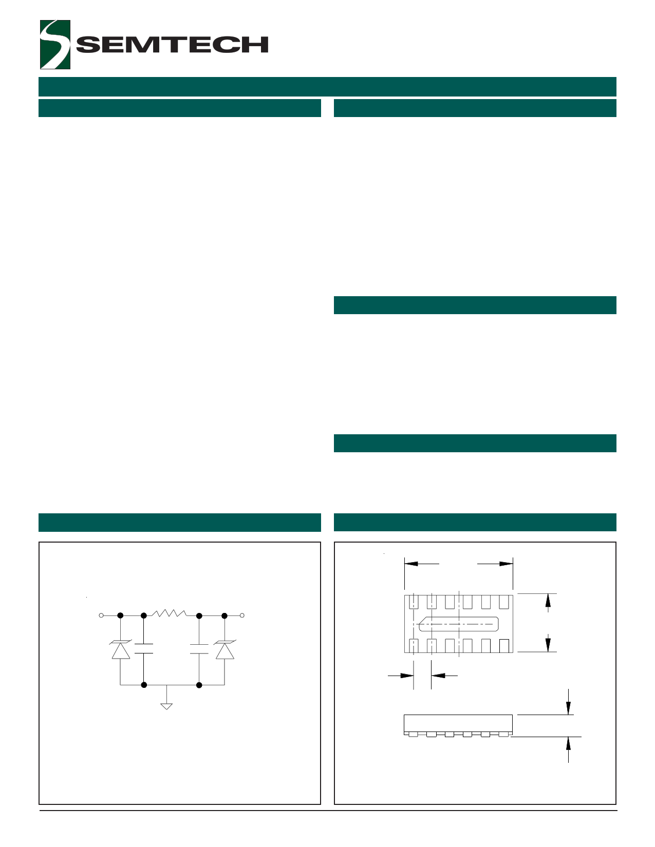
Circuit Diagram (Each Line)
Package Configuration
100 Ω
IN
OUT
10pF 10pF
3.00
12
1.60
0.50 BSC
GND
0.58
Device Schematic (6X)
Revision 12/6/2005
12 Pin SLP package (Bottom Side View)
Nominal Dimensions in mm
1 www.semtech.com
1 page 
EClamp2376P
PROTECTION PRODUCTS
Applications Information
PRELIMINARY
Figure 3 shows the recommended device layout. The
ground pad vias have a diameter of 0.008 inches
(0.20 mm) while the two external vias have a diameter
of 0.010 inches (0.250mm). The internal vias are
spaced approximately evenly from the center of the
pad. The designer may choose to use more vias with a
smaller diameter (such as 0.005 inches or 0.125mm)
since changing the diameter of the via will result in
little change in inductance (i.e. the log function in
Equation 2 in highly insensitive to parameter d) .
Figure 4 shows a typical insertion loss (S21) plot for
the device using Semtech’s filter evaluation board with
50 Ohm traces and the recommended via configura-
tion. Figure 5 shows a typical insertion loss (S21) plot
using a similar board without the internal ground pad
vias. The result is a more inductive ground loop. Note
the “hump” at a frequency of 2.5GHz. This is the
resonant frequency of the higher ground loop induc-
tance.
Figure 4 - Filter Characteristics Using Recommended
Layout with Internal Vias
CH1 S21 LOG 6 dB / REF 0 dB
0 dB
-6 dB
-12 dB
-18 dB
-24 dB
-30 dB
-36 dB
-42 dB
-48 dB
1
MHz
START. 030 MHz
10
MHz
1
2
1: -9.1473 dB
297.671 MHz
2: -19.559 dB
900 MHz
3: -30.645 dB
1.8 GHz
4: -34.705 dB
2.5 GHz
34
100
MHz
13
GHz GHz
STOP 3000.000000 MHz
Figure 3 - Recommended Layout Using Ground Vias
Figure 5 - Filter Characteristics Using Layout without
Internal Ground Vias
CH1 S21 LOG 6 dB / REF 0 dB
0 dB
-6 dB
-12 dB
-18 dB
-24 dB
-30 dB
-36 dB
1
MHz
START. 030 MHz
10
MHz
1: -8.9400 dB
288.002 MHz
2: -20.032 dB
900 MHz
3: -23.761 dB
1.8 GHz
4: -16.085 dB
2.5 GHz
1
4
2
3
100
MHz
13
GHz GHz
STOP 3000.000000 MHz
2005 Semtech Corp.
5
www.semtech.com
5 Page | ||
| Páginas | Total 8 Páginas | |
| PDF Descargar | [ Datasheet EClamp2376P.PDF ] | |
Hoja de datos destacado
| Número de pieza | Descripción | Fabricantes |
| EClamp2376K | ESD/EMI Protection | Semtech |
| EClamp2376P | ESD/EMI Protection | Semtech |
| Número de pieza | Descripción | Fabricantes |
| SLA6805M | High Voltage 3 phase Motor Driver IC. |
Sanken |
| SDC1742 | 12- and 14-Bit Hybrid Synchro / Resolver-to-Digital Converters. |
Analog Devices |
|
DataSheet.es es una pagina web que funciona como un repositorio de manuales o hoja de datos de muchos de los productos más populares, |
| DataSheet.es | 2020 | Privacy Policy | Contacto | Buscar |