|
|
|
PDF PI6ULS5V9617A Data sheet ( Hoja de datos )
| Número de pieza | PI6ULS5V9617A | |
| Descripción | Level Translating Fast-Mode PlusI2C-bus/SMbus Repeater | |
| Fabricantes | Pericom Semiconductor | |
| Logotipo | ||
Hay una vista previa y un enlace de descarga de PI6ULS5V9617A (archivo pdf) en la parte inferior de esta página. Total 13 Páginas | ||
|
No Preview Available !
PI6ULS5V9617A
|||||||||||||||||||||||||||||||||||||||||||||||||||||||||||||||||||||||||||||||||||||||||||||||||||||||||||||||||||||||||||||||||||||||||||||||||||||||||||||||||||||||||||||||||||||||||||||||||||||||||||||||||||||||||||||||||||||||||||||||||||||||||||||||||||||||||||||||||||||||||||||||||||||||||||||||||||||||||||||||||||||||
Level Translating Fast-Mode Plus I2C-bus/SMbus Repeater
Features
2 channel, bidirectional buffer isolates capacitance
and allows 540pF on either side of the device at 1
MHz and up to 4000 pF at lower speeds
Voltage level translation from 0.6V to 5.5V and
from 2.2V to 5.5V
Footprint and functional replacement for
PI6ULS5V9617A at Fast-mode speeds
Port A operating supply voltage range of 0.6V to
5.5V with normal levels(0.4VCC(A) + 0.8V ≤ VCC(B) )
Port B operating supply voltage range of 2.2V to
5.5V with static offset level
5V tolerant I2C-bus and enable pins
0 Hz to 1 MHz clock frequency (the maximum
system operating frequency may be less than 1MHz
because of the delays added by the repeater)
Active HIGH repeater enable input referenced to
VCC(B)
Open-drain input/outputs
Latching free operation
Supports arbitration and clock stretching across the
repeater
Accommodates Standard-mode, Fast-mode and
Fast-mode Plus I2C-bus devices, SMBus (standard
and high power mode), PMBus and multiple
masters
Powered-off high-impedance I2C-bus pins
ESD protection exceeds 8000V HBM per JESD22-
A114
Package: MSOP-8L, SOIC-8L and TDFN2x3-8L
Description
The PI6ULS5V9617A is a CMOS integrated circuit
intended for Fast-mode Plus (Fm+) I2C-bus or SMBus
applications. It can provide level shifting between low
voltage (down to 0.6V) and higher voltage (2.2V to 5.5V)
in mixed-mode applications.
The PI6ULS5V9617A enables the system designer
to isolate two halves of a bus for both voltage and
capacitance, accommodating more I2C devices or longer
trace length. It also permits extension of the I2C-bus by
providing bidirectional buffering for both the data (SDA)
and the clock (SCL) lines, thus enabling two buses of
540 pF at 1 MHz or up to 4000 pF at lower speeds. The
SDA and SCL pins are overvoltage tolerant and are
high-impedance when the PI6ULS5V9617A is
unpowered.
The 2.2V to 5.5V bus port B drivers have the static
level offset, while the adjustable voltage bus port A
drivers eliminate the static offset voltage. This results in
a LOW on the port B translating into a nearly 0V LOW
on the port A which accommodates the smaller voltage
swings of lower voltage logic. The EN pin is referenced
to VCC(B) and can also be used to turn the drivers on and
off under system control.
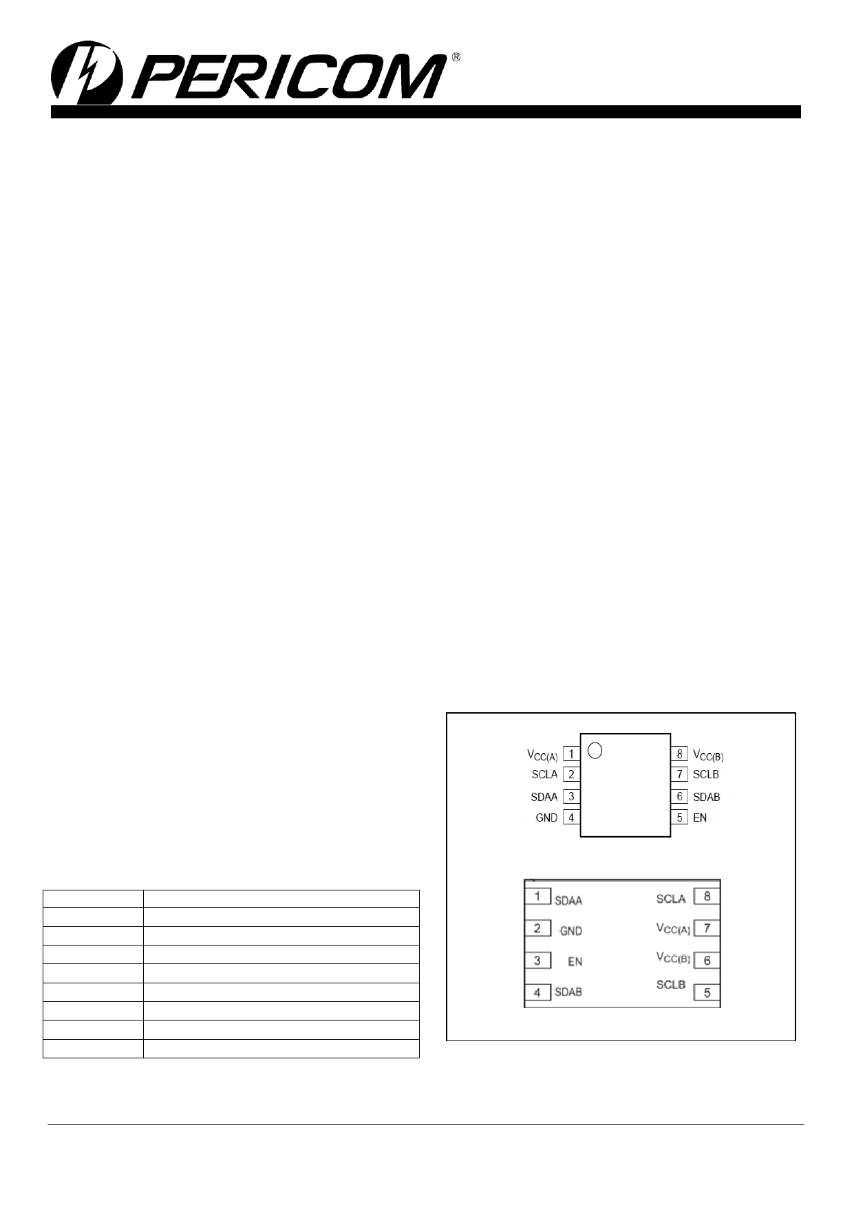
Pin Configuration
Pin Description
MSOP-8L, SOIC-8L(Top View)
Pin Name
VCC(A)
SCLA
SDAA
GND
EN
SDAB
SCLB
VCC(B)
Description
port A supply voltage (0.6V to 5.5V)
serial clock port A bus
serial data port A bus
supply ground (0 V)
active HIGH repeater enable input
serial data port B bus
serial clock port B bus
port B supply voltage (2.2V to 5.5V)
TDFN2*3-8L(Top View)
2014-03-0003
PT0482-3 04/09/14
1
1 page 
PI6ULS5V9617A
Level Translating Fast-Mode
Plus I2C-bus/SMbus Repeater
|||||||||||||||||||||||||||||||||||||||||||||||||||||||||||||||||||||||||||||||||||||||||||||||||||||||||||||||||||||||||||||||||||||||||||||||||||||||||||||||||||||||||||||||||||||||||||||||||||||||||||||||||||||||||||||||||||||||||||||||||||||||||||||||||||||||||||||||||||||||||||||||||||||||||||||||||||||||||||||||||||||||
Dynamic characteristics
VCC(A) = 0.6V to 5.5V(8); VCC(B) = 2.2V to 5.5V; GND = 0V; TA = -40°C to +85°C; Typical values measured with VCC(A) = 0.95V
and VCC(B) = 2.5V, unless otherwise noted.(1)(2)
Symbol
Parameter
Conditions
Min Typ[3] Max
Unit
tPLH
tPLH2[4]
tPHL
tTLH[5]
LOW-to-HIGH propagation delay
LOW-to-HIGH propagation delay2
HIGH-to-LOW propagation delay
LOW-to-HIGH transition time
B-side to A-side
B-side to A-side
B-side to A-side
A-side
- -52 -103
- 94 130
- 76 152
- 60
-
ns
ns
ns
ns
SRf
tPLH[6]
tPHL[6]
tTLH
Falling slew rate
LOW-to-HIGH propagation delay
HIGH-to-LOW propagation delay
LOW-to-HIGH transition time
port A; 0.7VCC(A) to 0.3VCC(A)
A-side to B-side
A-side to B-side
B-side
- 0.037
-
- 45 102
- 50 173
- 60
-
ns
ns
ns
ns
tTHL HIGH-to-LOW transition time B-side
- 30
76
ns
ten[7] Enable time
Quiescent -0.3 V; EN HIGH to
enable;
-
-
100
ns
tdis[7]
Disable time
quiescent + 0.3 V;
EN LOW to disable;
- - 100 ns
Note:
(1) Times are specified with loads of 1.35 kΩ pull-up resistance and 50 pF load capacitance on port A and port B, and a falling
edge slew rate of 0.05 V/ns input signals.
(2) Pull-up voltages are VCC(A) on port A and VCC(B) on port B.
(3) Typical values were measured with VCC(A) = 0.95 V,VCC(B)=2.5V at TA = 25°C, unless otherwise noted.
(4) The tPLH2 delay data from port B to port A is measured at 0.45 V on port B to 0.5VCC(A) on port A.
(5) The tTLH of the bus is determined by the pull-up resistance (1.35 k Ω) and the total capacitance (50 pF).
(6) The proportional delay data from port A to port B is measured at 0.5VCC(A) on port A to 0.5VCC(B) on port B.
(7) The enable pin, EN, should only change state when the global bus and the repeater port are in an idle state.
(8) VCC(A) may be as high as 5.5 V for over voltage tolerance but 0.4VCC(A) + 0.8 V ≤ VCC(B) for the channels to be enabled and
functional normally.
Figure 5: Propagation Delay and Transition Times BA
Figure 6: Propagation Delay and Transition Times A→B
2014-03-0003
Figure7: Propagation Delay and Enable and disable time
PT0482-3 04/09/14
5
5 Page 
PI6ULS5V9617A
Level Translating Fast-Mode
Plus I2C-bus/SMbus Repeater
|||||||||||||||||||||||||||||||||||||||||||||||||||||||||||||||||||||||||||||||||||||||||||||||||||||||||||||||||||||||||||||||||||||||||||||||||||||||||||||||||||||||||||||||||||||||||||||||||||||||||||||||||||||||||||||||||||||||||||||||||||||||||||||||||||||||||||||||||||||||||||||||||||||||||||||||||||||||||||||||||||||||
SOIC-8L
2014-03-0003
PT0482-3 04/09/14
11
11 Page | ||
| Páginas | Total 13 Páginas | |
| PDF Descargar | [ Datasheet PI6ULS5V9617A.PDF ] | |
Hoja de datos destacado
| Número de pieza | Descripción | Fabricantes |
| PI6ULS5V9617A | Level Translating Fast-Mode PlusI2C-bus/SMbus Repeater | Pericom Semiconductor |
| Número de pieza | Descripción | Fabricantes |
| SLA6805M | High Voltage 3 phase Motor Driver IC. |
Sanken |
| SDC1742 | 12- and 14-Bit Hybrid Synchro / Resolver-to-Digital Converters. |
Analog Devices |
|
DataSheet.es es una pagina web que funciona como un repositorio de manuales o hoja de datos de muchos de los productos más populares, |
| DataSheet.es | 2020 | Privacy Policy | Contacto | Buscar |