|
|
|
PDF SMB110 Data sheet ( Hoja de datos )
| Número de pieza | SMB110 | |
| Descripción | Five Channel Programmable DC-DC System Power Manager | |
| Fabricantes | Summit | |
| Logotipo | ||
Hay una vista previa y un enlace de descarga de SMB110 (archivo pdf) en la parte inferior de esta página. Total 30 Páginas | ||
|
No Preview Available !
Five Channel Programmable DC-DC System Power Manager
SMB110
Preliminary Information
FEATURES & APPLICATIONS
• Digital programming of all major parameters via I2C
interface and non-volatile memory
o Output voltage set point
o Output power-up/down sequencing
o Input/Battery voltage monitoring
o Digital soft-start and output slew rate
o Output voltage margining
o UV/OV monitoring of all outputs
o Enable/Disable outputs independently
• Five output channels
o Two synchronous step-down (buck) channels
o One step-up (boost) channel
o One inverting (buck-boost) channel
o One fixed output +3.3V LDO
• User friendly Graphical User Interface (GUI)
• +2.7V to +6.0V Input Range
• Highly accurate reference and output voltage (<0.5%)
with Active DC Output Control (ADOC™) technology
• Undervoltage Lockout (UVLO) with hysteresis
• 800 kHz operating frequency
• 96 bytes of user configurable nonvolatile memory
Applications
• Digital camcorders/still cameras
• Portable DVD/MP3/GPS
• Camera/smart phones
• TFT Displays/Monitors/TV’s
• Mobile Computing/PDA’s
• Consumer battery-operated equipment
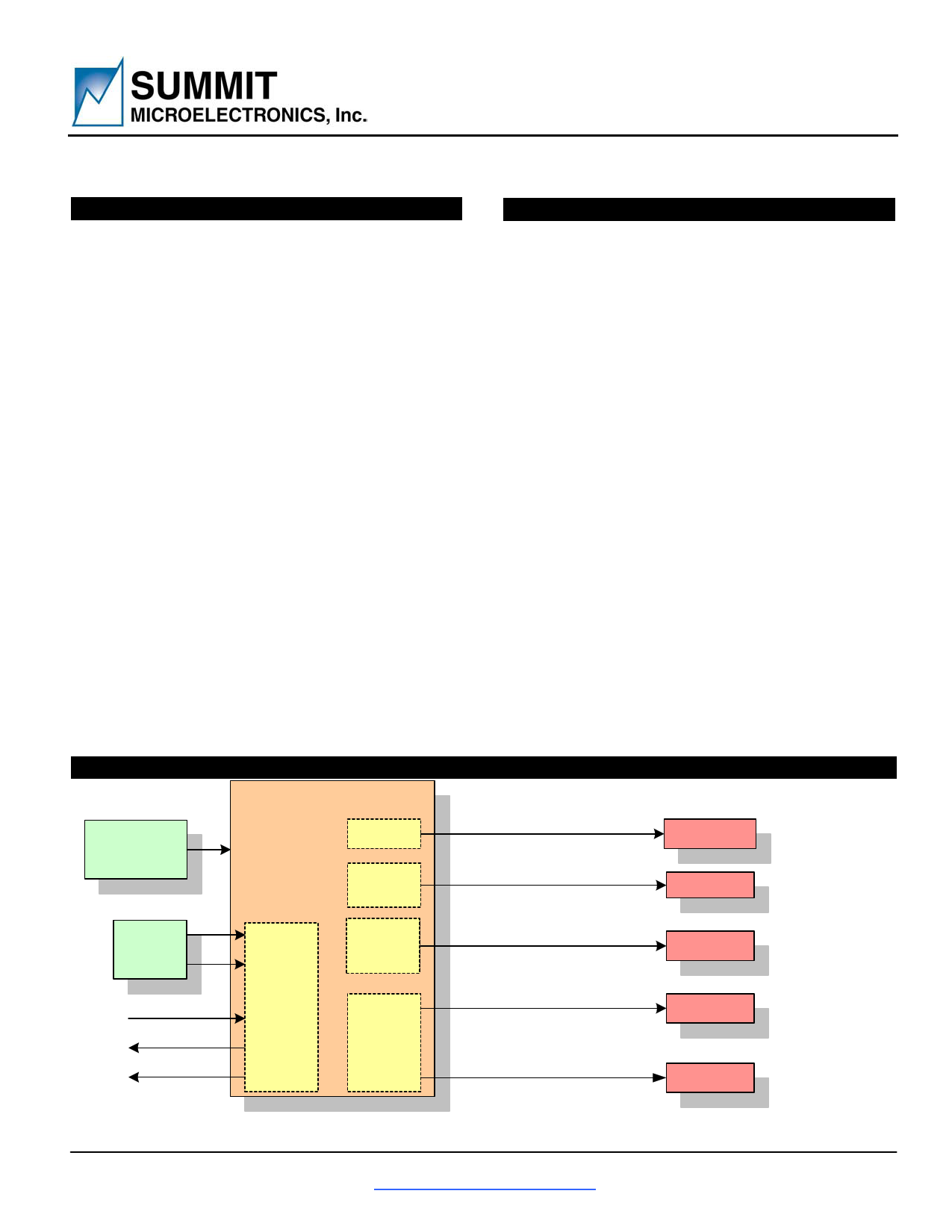
SIMPLIFIED APPLICATIONS DRAWING
SMB110
INTRODUCTION
The SMB110 is a highly integrated and flexible five-channel
power manager designed for use in a wide range of portable
applications. The built-in digital programmability allows system
designers to custom tailor the device to suit almost any multi-
channel power supply application from digital camcorders to
mobile phones. Complete with a user friendly GUI, all
programmable settings including output voltages and
input/output voltage monitoring can be customized with ease.
The SMB110 integrates all the essential blocks required to
implement a complete five-channel power subsystem including
two synchronous step-down “buck” controllers, one step-up
“boost” controller, one inverting “buck-boost” controller and one
fixed output +3.3V LDO. Additionally sophisticated power
control/monitoring functions required by complex systems are
built-in. These include digitally programmable output voltage
set point, power-up/down sequencing, enable/disable,
margining and UV/OV/input/output monitoring on all channels.
The integration of features and built-in flexibility of the SMB110
allows the system designer to create a “platform solution” that
can be easily modified via software without major hardware
changes. Combined with the re-programmability of the
SMB110 this facilitates rapid design cycles and proliferation
from a base design to future generations of product.
The SMB110 is suited to battery-powered applications with an
input range of +2.7V to +6.0V. Output voltages are extremely
accurate (<0.5%) employing proprietary ADOC™ technology.
Communication is via the industry standard I2C bus. All user-
programmed settings are stored in non-volatile EEPROM of
which 96 bytes may be used for general-purpose memory
applications. The operating temperature range is +0C to +70C
and the available package is a lead-free, Green, RoHS
compliant, 32-pad QFN-32.
+2.7V to +6.0V
or
Li-Ion
LDO
Inverter
Channel
+3.3V @20mA
MCU/RTC
-0.8V to -30V (Prog.) @UP TO1A
CCD
I2C/SMBus
Reset Input
Reset Output
Power Good
System
Control and
Monitoring
Step-Up
(Boost)
Channels
2 Step-
Down
(Buck)
Channels
Vin to +30V (Prog.) @ UP TO 1A
TFT/LCD
+0.8V to 0.9 x Vin (Prog.) @ 2A
Memory, I/O
+0.8V to 0.9 x Vin (Prog.) @ 2A
CPU Core
Figure 1 – Applications diagram featuring the SMB110 five-channel, programmable DC-DC controller
Note: This is an applications example only. Some pins, components and values are not shown.
© SUMMIT Microelectronics, Inc. 2005
1717 Fox Drive • San Jose CA 95131 •
http://www.summitmicro.com/
2099 2.3 5/3/2005
Phone 408 436-9890 • FAX 408 436-9897
1
1 page 
INTERNAL BLOCK DIAGRAM
COMP2_CH[2,3]
VM_CH[2,3]
100k
z
z
–
+ OA
z
CLAMP
COMP1_CH[2,3]
VREF
DIGITAL TO
ANALOG
CONVERTER
COMP2_CH1
VDD_CAP
zz
LEVEL
SHIFTER
VREF
+
–
+
–
– OA
z ++
z
CLAMP
COMP1_CH1
I2C/SMBUS
SDA
SCL
zz
LEVEL
SHIFTER
VREF
+
–
+
–
z–
OA
z+
z
CLAMP
z
LEVEL
SHIFTER
VREF
–
+
–
+
+ DUTY
–
CYCLE
LIMIT
MAX LIMIT
OSC
Fixed 800kHzLOW LIMIT
GLITCH
FILTER
OVER VOLTAGE
DETECTION
GLITCH
FILTER
UNDER VOLTAGE
DETECTION
+ DUTY
–
CYCLE
LIMIT
OSC
MAX LIMIT
Fixed 800kHz LOW LIMIT
GLITCH
FILTER
OVER VOLTAGE
DETECTION
GLITCH
FILTER
UNDER VOLTAGE
DETECTION
+ DUTY
–
CYCLE
LIMIT
OSC
MAX LIMIT
Fixed 800kHz LOW LIMIT
GLITCH
FILTER
OVER VOLTAGE
DETECTION
GLITCH
FILTER
UNDER VOLTAGE
DETECTION
VBATT
z
VDD_CAP
2.5V
REGULATOR
LDO
zz
BANDGAP VREF
z
z+
–
UV2 z
zD Q
nBATT_FAULT
LEVEL
SHIFTER
+ UV1
–
SMB110
Preliminary Information
Channel 2 and 3
Synchronous buck
PWM Converter
HVSUP[2,3]
HSDRV[2,3]
DEADTIME
LSDRV[2,3]
SEQUENCING
LOGIC
ENABLE
ENABLE
ENABLE
z
100u
COMP
+
–
0.2 V
PWREN0
Channel 1
boost
PWM Converter
with Shutoff
PCHSEQ_CH1
LSDRV1
DRIVER
Channel 0
Negative
PWM Converter
LSDRV0
DRIVER
COMP1_CH0
COMP2_CH0
LEVEL
SHIFTER
X2 VREF_OUT
VREF
LDO_SUPPLY
Channel 5
Standby Series-Pass LDO
VSTANDBY
GND
Summit Microelectronics, Inc
2099 2.3 3/1/2005
5
5 Page 
SMB110
Preliminary Information
DC OPERATING CHARACTERISTICS (CONTINUED)
(Over recommended operating conditions, unless otherwise noted. All voltages are relative to GND.)
Symbol
Parameter
Conditions
Min Typ Max
Unit
Error Amplifier
VACC
TS
Threshold Voltage accuracy
Temperature stability
AVOL
BW
Open loop voltage Gain
Frequency bandwidth
ISOURCE
ISINK
LDO
Output source current
Output sink current
VOUT
Nominal output voltage
∆VOUT
∆VLOAD
∆VLINE
PSRR
IQ
Output voltage accuracy
Load regulation error
Line regulation error
Power supply rejection ratio
Quiescent current
VDO Dropout voltage
ILIMIT
Maximum output current
VN Output Noise voltage
Inverting Output Block Channel 0
VOUT
Programmable voltage set point
range
∆VOUT
VCOMP1
∆ VCOMP1
Output accuracy
Feedback voltage reference
Feedback voltage reference
accuracy
RON LSDRV Output ON resistance
D.C.
LSDRV Duty Cycle
VREF_OUT
Level shift voltage reference
At DC
At AV=0 dB
At 0.5V
At 0.5V
LDO_SUPPLY = 4.2V,
ILOAD=0A
Percent of 3.3V output @
10mA, LDO_SUPPLY = 4.2V
No load
20log(Vout/Vin) @ 10kHz
VBATT = 4.2V, ILOAD=0A
IOUT = 1 mA
IOUT = 5 mA
IOUT = 10 mA
IOUT = 15 mA
IOUT = 20 mA
Peak to peak
0.2 %
0.2 %
60 dB
30 MHz
20 µA
800 µA
3.3
0.3
0.3
0.17
50
50
20
100
200
300
400
1
V
%
%/V
%/mA
dB
µA
mV
40 mA
mV
VBATT=4.2V, ILOAD=0
-35 -0.5
Excluding external resistor
divider accuracy
COMP1 pin
0.5
1.0
COMP1 pin
-0.2 +0.2
ROH
ROL
17
3
High
85 95
Low 5 15
VREF_OUT pin programmable
in 8mV steps
1
2
V
%
V
%
Ω
%
V
Summit Microelectronics, Inc
2099 2.3 3/1/2005
11
11 Page | ||
| Páginas | Total 30 Páginas | |
| PDF Descargar | [ Datasheet SMB110.PDF ] | |
Hoja de datos destacado
| Número de pieza | Descripción | Fabricantes |
| SMB11 | SURFACE MOUNT UNIDIRECTIONAL AND BIDIRECTIONAL TRANSIENT VOLTAGE SUPPRESSORS | Lite-On Technology |
| SMB11 | TVS Diode, SMD (Transient Voltage Suppressor) | MIC GROUP RECTIFIERS |
| SMB110 | Five Channel Programmable DC-DC System Power Manager | Summit |
| SMB110 | SURFACE MOUNT UNIDIRECTIONAL AND BIDIRECTIONAL TRANSIENT VOLTAGE SUPPRESSORS | Lite-On Technology |
| Número de pieza | Descripción | Fabricantes |
| SLA6805M | High Voltage 3 phase Motor Driver IC. |
Sanken |
| SDC1742 | 12- and 14-Bit Hybrid Synchro / Resolver-to-Digital Converters. |
Analog Devices |
|
DataSheet.es es una pagina web que funciona como un repositorio de manuales o hoja de datos de muchos de los productos más populares, |
| DataSheet.es | 2020 | Privacy Policy | Contacto | Buscar |