|
|
|
PDF ISL8117A Data sheet ( Hoja de datos )
| Número de pieza | ISL8117A | |
| Descripción | Synchronous Step-Down PWM Controller | |
| Fabricantes | Intersil | |
| Logotipo | ||
Hay una vista previa y un enlace de descarga de ISL8117A (archivo pdf) en la parte inferior de esta página. Total 23 Páginas | ||
|
No Preview Available !
DATASHEET
Synchronous Step-Down PWM Controller
ISL8117A
The ISL8117A is a synchronous buck controller to generate
POL voltage rails and bias voltage rails for a wide variety of
applications in industrial and general purpose segments. Its
wide input and output voltage ranges make it suitable for
telecommunication and after-market automotive applications.
ISL8117A is a derivative from the ISL8117 by replacing its
CLKOUT pin with COMP pin to provide flexibility to customers to
configure the voltage loop compensation externally.
The ISL8117A uses the valley current modulation technique to
bring a hassle-free power supply design with minimal number
of components and complete protection from unwanted
events.
The ISL8117A offers programmable soft-start and enable
functions along with a power-good indicator for ease of supply
rail sequencing and other housekeeping requirements. In ideal
situations, a complete power supply circuit can be designed
with 10 external components and provide OV/OC/OT
protections in a space conscious 16 Ld 4mmx4mm QFN
package. The package uses an EPAD to improve thermal
dissipation and noise immunity. Low pin count, less number of
external components and default internal values, makes the
ISL8117A an ideal solution for quick to market simple power
supply designs. The ISL8117A utilizes single resistor settings
for other functions such as operating frequency and
overcurrent protection. Its current mode control with VIN
feed-forward enables it to cover various applications. The
unique DEM/Skipping mode at light load dramatically lowers
standby power consumption with consistent output ripple over
different load levels.
Related Literature
• UG049, “ISL8117AEVAL1Z Evaluation Board User Guide”
• UG050, “ISL8117AEVAL2Z Evaluation Board User Guide”
Features
• Wide input voltage range: 4.5V to 60V
• Wide output voltage range: 0.6V to 54V
• Light-load efficiency enhancement
- Low ripple diode emulation mode with pulse skipping
• Programmable soft-start
• Supports prebiased output with SR soft-start
• Programmable frequency: 100kHz to 2MHz
• External sync
• PGOOD indicator
• Forced PWM
• Adaptive shoot-through protection
• No external current sense resistor
- Use lower MOSFET rDS(ON)
• Functional pins with default design values
- EN, RT, SS/TRK, MOD/SYNC, LGATE/OCS
• Complete protection
- Overcurrent, overvoltage, over-temperature, undervoltage
• Pb-free (RoHS compliant)
Applications
• PLC and factory automation
• Industrial equipments
• Security surveillance
• Server and data centers
• Switcher and routers
• Telecom and datacom
• LED panels
16
1 MOD
SYNC
2 PGO OD
3 RT
4
SS
TRK
5
15 14
ISL811 7A
SGND
67
13
UGATE 12
PHASE 11
ISEN 10
VCC5V 9
8
VIN
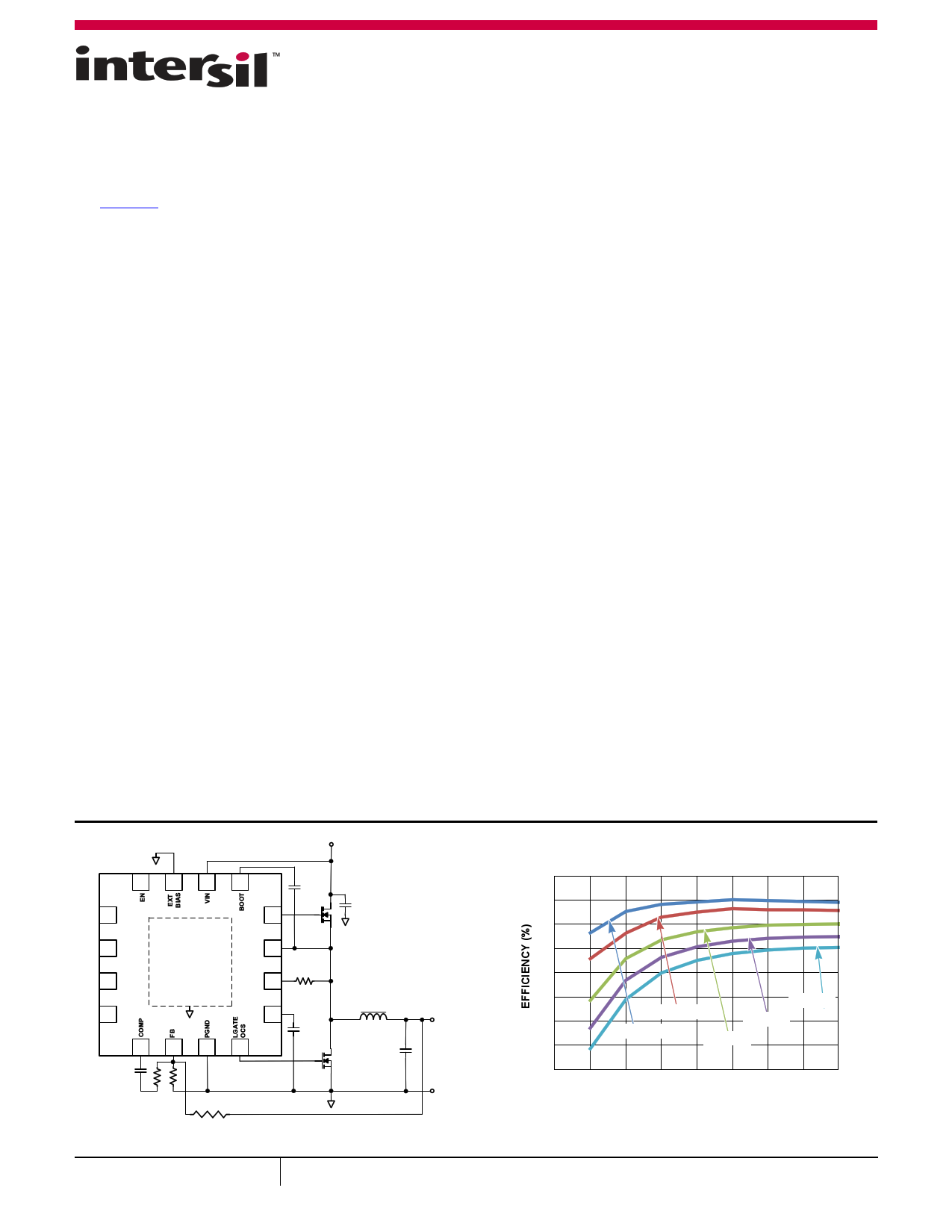
FIGURE 1. TYPICAL APPLICATION
August 31, 2015
FN8752.0
1
100
98
96
94
92
VOUT
90
88
VIN = 24V
VIN = 60V
VIN = 48V
86
VIN = 18V
VIN = 36V
840 2 4 6 8 10 12 14 16
OUTPUT CURRENT (A)
FIGURE 2. EFFICIENCY
CAUTION: These devices are sensitive to electrostatic discharge; follow proper IC Handling Procedures.
1-888-INTERSIL or 1-888-468-3774 | Copyright Intersil Americas LLC 2015. All Rights Reserved
Intersil (and design) is a trademark owned by Intersil Corporation or one of its subsidiaries.
All other trademarks mentioned are the property of their respective owners.
1 page 
Block Diagram
BOOT
UGATE
PHASE
5VCC
LGATE/OCS
PGND LGATE/OCS
ISL8117A
5VCC
ADAPTIVE
DEAD TIME
V/I SAMPLE TIMING
PGOOD EN
VIN VCC5V
SS/TRK
POR
ENABLE
BIAS SUPPLIES
REFERENCE
FAULT LATCH
(Note 6)
EXTBIAS
+
- SW THRES.
COMP
PGND
FB
-
+
+
-
0.6V
REF
SS/TRK
ISEN
CURRENT
SAMPLE
+
-
LGATE/OCS
OC OV/UV
2µA
SS/TRK
CURRENT
SAMPLE
FB
PWM
+
-
5VCC
VIN
DUTY CYCLE
RAMP GENERATOR
CLOCK
MOD/SYNC
+ 1.75V
- REFERENCE
+
OC
- SAME STATE FOR
2 CLOCK CYCLES
REQUIRED TO LATCH
OVERCURRENT FAULT
FIGURE 3. BLOCK DIAGRAM
RT
SGND
Submit Document Feedback
5
FN8752.0
August 31, 2015
5 Page 
ISL8117A
Typical Performance Curves Oscilloscope plots are taken using the ISL8117AEVAL1Z evaluation board, VIN = 18V to
60V, VOUT = 12V, IOUT = 20A unless otherwise noted. (Continued)
605 120
604
603 100
602 80
601
600 60
599
598 40
597
20
596
595
-40 -25 -10 5 20 35 50 65 80 95 110 125
TEMPERATURE (°C)
FIGURE 12. REFERENCE VOLTAGE vs TEMPERATURE
0
0 0.5 1.0 1.5 2.0 2.5 3.0
SOFT-START PIN VOLTAGE (V)
FIGURE 13. NORMALIZED OUTPUT VOLTAGE vs VOLTAGE ON
SOFT-START PIN
3.5
100
90
80
70 VIN = 24V
60
50
40 VIN = 18V
30
VIN = 60V
VIN = 48V
20 VIN = 36V
10
0
0.01
0.1 1
IOUT (A)
FIGURE 14. CCM MODE EFFICIENCY
10
20
100
90
80
70
60
50
40
30
20
10
0
0.01
VIN = 24V
VIN = 18V
VIN = 60V
VIN = 48V
VIN = 36V
0.1 1
IOUT (A)
FIGURE 15. DEM MODE EFFICIENCY
10 20
1.0
0.8
0.6
0.4
0.2 VIN = 24V
0.0
-0.2 VIN = 18V
-0.4 VIN = 36V
-0.6
VIN = 48V
VIN = 60V
-0.8
-1.0
0 2 4 6 8 10 12 14 16 18 20
OUTPUT CURRENT (A)
FIGURE 16. CCM MODE LOAD REGULATION
Submit Document Feedback 11
1.0
0.8
0.6 IO = 10A
IO = 20A
0.4
0.2
0.0
-0.2
-0.4 IO = 0A
-0.6
-0.8
-1.0
18
24 30 36 42 48 54
VIN (V)
FIGURE 17. CCM MODE LINE REGULATION
60
FN8752.0
August 31, 2015
11 Page | ||
| Páginas | Total 23 Páginas | |
| PDF Descargar | [ Datasheet ISL8117A.PDF ] | |
Hoja de datos destacado
| Número de pieza | Descripción | Fabricantes |
| ISL8117 | Synchronous Step-down PWM Controller | Intersil Corporation |
| ISL8117A | Synchronous Step-Down PWM Controller | Intersil |
| Número de pieza | Descripción | Fabricantes |
| SLA6805M | High Voltage 3 phase Motor Driver IC. |
Sanken |
| SDC1742 | 12- and 14-Bit Hybrid Synchro / Resolver-to-Digital Converters. |
Analog Devices |
|
DataSheet.es es una pagina web que funciona como un repositorio de manuales o hoja de datos de muchos de los productos más populares, |
| DataSheet.es | 2020 | Privacy Policy | Contacto | Buscar |