|
|
|
PDF MAX3109 Data sheet ( Hoja de datos )
| Número de pieza | MAX3109 | |
| Descripción | Dual Serial UART | |
| Fabricantes | Maxim Integrated | |
| Logotipo | ||
Hay una vista previa y un enlace de descarga de MAX3109 (archivo pdf) en la parte inferior de esta página. Total 30 Páginas | ||
|
No Preview Available !
MAX3109
Dual Serial UART with 128-Word FIFOs
General Description
The MAX3109 advanced dual universal asynchronous
receiver-transmitter (UART) has 128 words of receive and
transmit first-in/first-out (FIFO) and a high-speed SPI or
I2C controller interface. The 2x and 4x rate modes allow
a maximum of 24Mbps data rates. A phase-locked loop
(PLL) and the fractional baud-rate generators allow a high
degree of flexibility in baud-rate programming and refer-
ence clock selection.
Independent logic-level translation on the transceiver and
controller interfaces allows ease of interfacing to micro-
controllers, FPGAs, and transceivers that are powered
by differing supply voltages. Automatic hardware and
software flow control with selectable FIFO interrupt trig-
gering offloads low-level activity from the host controller.
Automatic half-duplex transceiver control with program-
mable setup and hold times allow the MAX3109 to be
used in high-speed applications such as PROFIBUSDP.
The 128-word FIFOs have advanced FIFO control, reduc-
ing host processor data flow management.
The MAX3109 is available in a 32-pin TQFN (5mm x
5mm) package and is specified over the -40°C to +85°C
extended temperature range.
Applications
●● Handheld Devices
●● Power Meters
●● Programmable Logic
Controllers (PLCs)
●● Medical Systems
●● Point-of-Sales Systems
●● HVAC or Building Control
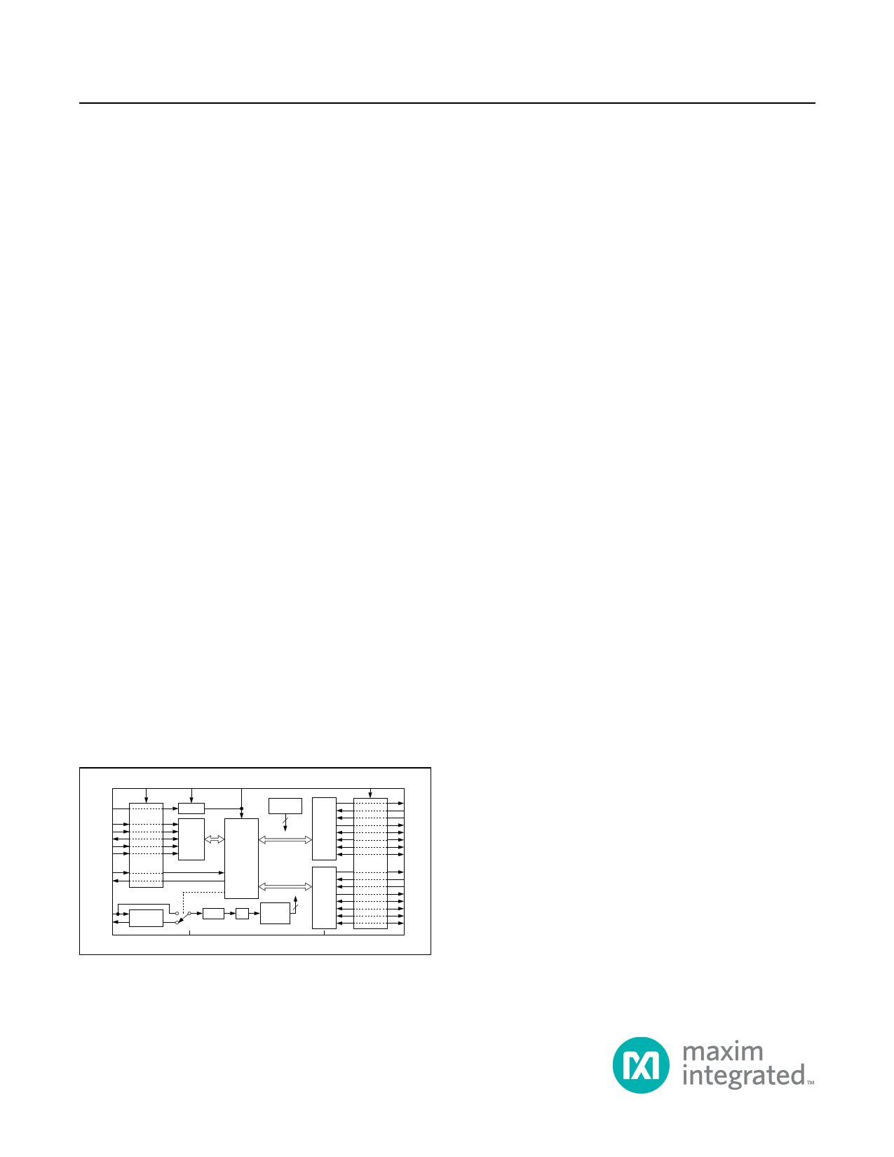
Functional Diagram
LDOEN
SPI/I2C
MOSI/A1
MISO/SDA
CS/A0
SCLK/SCL
RST
IRQ
XIN
XOUT
VL VCC
LOGIC-LEVEL
TRANSLATION
LDO
SPI
AND
I2C
INTERFACE
V18
TRANSMITTER
SYNC
2
UART0
REGISTERS
AND
CONTROL
MAX3109
CRYSTAL
OSCILLATOR
FRACTIONAL 2
DIVIDER PLL BAUD-RATE
GENERATOR
AGND
UART1
DGND
VEXT
LOGIC-LEVEL
TRANSLATION
TX0
RX0
CTS0
RTS0
GPIO0
GPIO1
GPIO2
GPIO3
TX1
RX1
CTS1
RTS1
GPIO4
GPIO5
GPIO6
GPIO7
IrDA is a service mark of Infrared Data Association Corporation.
Benefits and Features
●● Bridges an SPI/MICROWIRE or I2C Microprocessor
Bus to an Asynchronous Interface Such as RS-485,
RS-232, or IrDASM
• SIR- and MIR-Compliant IrDA Encoder/Decoder
• Line Noise Indication Ensures Data Link Integrity
●● Deep, 128-Word Buffer and Automated Control
Features Help Offload Activity on the Microcontroller
• Automatic RTS_ and CTS_ Flow Control
• Automatic XON/XOFF Software Flow Control
• 9-Bit Multidrop-Mode Data Filtering
-- Special Character Detection
-- GPIO-Based Character Detection
-- Two Timers Routed to GPIOs
-- 8 Flexible GPIOs with 20mA Drive Capability
●● Saves Board Space
• TQFN (5mm x 5mm) Package
• Dual UART in a Single Package
●● Fast Data Rates Allow Maximum System Flexibility
Across Interface Standards
• 24Mbps (max) Data Rate
• High-Resolution Programmable Baud-Rate
• SPI Up to 26MHz Clock Rate
• Fast Mode Plus I2C Up to 1MHz
●● Integrated Internal Oscillator Eliminates the Need for
an External Oscillator and Reduces the BOM Cost
• Integrated PLL and Divider
●● Power Management Control Features Minimize
Power Consumption for Portable Applications
• 1.71V to 3.6V Supply Range
• Shutdown and Autosleep Modes
-- 1μA Shutdown Current
●● Logic-Level Translation on the Controller and
Transceiver Interfaces Ensure System Compatibility
●● Register Compatible with MAX3107, MAX3108, and
MAX148301
19-5806; Rev 5; 8/16
1 page 
MAX3109
Dual Serial UART with 128-Word FIFOs
LIST OF TABLES
Table 1. StopBits Truth Table . . . . . . . . . . . . . . . . . . . . . . . . . . . . . . . . . . . . . . . . . . . . . . . . . . . . . . . . . . . . . . . . . . . . 40
Table 2. Lengthx Truth Table . . . . . . . . . . . . . . . . . . . . . . . . . . . . . . . . . . . . . . . . . . . . . . . . . . . . . . . . . . . . . . . . . . . . . 40
Table 3. SwFlow[3:0] Truth Table . . . . . . . . . . . . . . . . . . . . . . . . . . . . . . . . . . . . . . . . . . . . . . . . . . . . . . . . . . . . . . . . . 45
Table 4. PLLFactorx Selection Guide . . . . . . . . . . . . . . . . . . . . . . . . . . . . . . . . . . . . . . . . . . . . . . . . . . . . . . . . . . . . . . 49
Table 5. GloblComnd Command Descriptions . . . . . . . . . . . . . . . . . . . . . . . . . . . . . . . . . . . . . . . . . . . . . . . . . . . . . . . 53
Table 6. Extended Mode Addressing
(SPI Only) . . . . . . . . . . . . . . . . . . . . . . . . . . . . . . . . . . . . . . . . . . . . . . . . . . . . . . . . . . . . . . . . . . . . . . . . . . . . . . . . . . . 53
Table 7. SPI Command Byte Configuration . . . . . . . . . . . . . . . . . . . . . . . . . . . . . . . . . . . . . . . . . . . . . . . . . . . . . . . . . 57
Table 8. I2C Address Map . . . . . . . . . . . . . . . . . . . . . . . . . . . . . . . . . . . . . . . . . . . . . . . . . . . . . . . . . . . . . . . . . . . . . . . 59
LIST OF REGISTERS
Receive Hold Register (RHR) . . . . . . . . . . . . . . . . . . . . . . . . . . . . . . . . . . . . . . . . . . . . . . . . . . . . . . . . . . . . . . . . . . . . 29
Transmit Hold Register (THR) . . . . . . . . . . . . . . . . . . . . . . . . . . . . . . . . . . . . . . . . . . . . . . . . . . . . . . . . . . . . . . . . . . . . 29
IRQ Enable Register (IRQEn) . . . . . . . . . . . . . . . . . . . . . . . . . . . . . . . . . . . . . . . . . . . . . . . . . . . . . . . . . . . . . . . . . . . . 30
Interrupt Status Register (ISR) . . . . . . . . . . . . . . . . . . . . . . . . . . . . . . . . . . . . . . . . . . . . . . . . . . . . . . . . . . . . . . . . . . . 31
Line Status Interrupt Enable Register (LSRIntEn) . . . . . . . . . . . . . . . . . . . . . . . . . . . . . . . . . . . . . . . . . . . . . . . . . . . . 32
Line Status Register (LSR) . . . . . . . . . . . . . . . . . . . . . . . . . . . . . . . . . . . . . . . . . . . . . . . . . . . . . . . . . . . . . . . . . . . . . . 33
Special Character Interrupt Enable Register (SpclChrIntEn) . . . . . . . . . . . . . . . . . . . . . . . . . . . . . . . . . . . . . . . . . . . . 34
Special Character Interrupt Register (SpclCharInt) . . . . . . . . . . . . . . . . . . . . . . . . . . . . . . . . . . . . . . . . . . . . . . . . . . . 35
STS Interrupt Enable Register (STSIntEn) . . . . . . . . . . . . . . . . . . . . . . . . . . . . . . . . . . . . . . . . . . . . . . . . . . . . . . . . . . 36
Status Interrupt Register (STSInt) . . . . . . . . . . . . . . . . . . . . . . . . . . . . . . . . . . . . . . . . . . . . . . . . . . . . . . . . . . . . . . . . . 37
MODE1 Register . . . . . . . . . . . . . . . . . . . . . . . . . . . . . . . . . . . . . . . . . . . . . . . . . . . . . . . . . . . . . . . . . . . . . . . . . . . . . . 38
MODE2 Register . . . . . . . . . . . . . . . . . . . . . . . . . . . . . . . . . . . . . . . . . . . . . . . . . . . . . . . . . . . . . . . . . . . . . . . . . . . . . . 39
Line Control Register (LCR) . . . . . . . . . . . . . . . . . . . . . . . . . . . . . . . . . . . . . . . . . . . . . . . . . . . . . . . . . . . . . . . . . . . . . 40
Receiver Timeout Register (RxTimeOut) . . . . . . . . . . . . . . . . . . . . . . . . . . . . . . . . . . . . . . . . . . . . . . . . . . . . . . . . . . . 41
HDplxDelay Register . . . . . . . . . . . . . . . . . . . . . . . . . . . . . . . . . . . . . . . . . . . . . . . . . . . . . . . . . . . . . . . . . . . . . . . . . . . 41
IrDA Register . . . . . . . . . . . . . . . . . . . . . . . . . . . . . . . . . . . . . . . . . . . . . . . . . . . . . . . . . . . . . . . . . . . . . . . . . . . . . . . . . 42
Flow Level Register (FlowLvl) . . . . . . . . . . . . . . . . . . . . . . . . . . . . . . . . . . . . . . . . . . . . . . . . . . . . . . . . . . . . . . . . . . . . 42
FIFO Interrupt Trigger Level Register (FIFOTrgLvl) . . . . . . . . . . . . . . . . . . . . . . . . . . . . . . . . . . . . . . . . . . . . . . . . . . . 43
Transmit FIFO Level Register (TxFIFOLvl) . . . . . . . . . . . . . . . . . . . . . . . . . . . . . . . . . . . . . . . . . . . . . . . . . . . . . . . . . . 43
Receive FIFO Level Register (RxFIFOLvl) . . . . . . . . . . . . . . . . . . . . . . . . . . . . . . . . . . . . . . . . . . . . . . . . . . . . . . . . . . 43
Flow Control Register (FlowCtrl) . . . . . . . . . . . . . . . . . . . . . . . . . . . . . . . . . . . . . . . . . . . . . . . . . . . . . . . . . . . . . . . . . . 44
XON1 Register . . . . . . . . . . . . . . . . . . . . . . . . . . . . . . . . . . . . . . . . . . . . . . . . . . . . . . . . . . . . . . . . . . . . . . . . . . . . . . . 45
XON2 Register . . . . . . . . . . . . . . . . . . . . . . . . . . . . . . . . . . . . . . . . . . . . . . . . . . . . . . . . . . . . . . . . . . . . . . . . . . . . . . . 46
XOFF1 Register . . . . . . . . . . . . . . . . . . . . . . . . . . . . . . . . . . . . . . . . . . . . . . . . . . . . . . . . . . . . . . . . . . . . . . . . . . . . . . . 46
XOFF2 Register . . . . . . . . . . . . . . . . . . . . . . . . . . . . . . . . . . . . . . . . . . . . . . . . . . . . . . . . . . . . . . . . . . . . . . . . . . . . . . . 47
GPIO Configuration Register (GPIOConfg) . . . . . . . . . . . . . . . . . . . . . . . . . . . . . . . . . . . . . . . . . . . . . . . . . . . . . . . . . 47
www.maximintegrated.com
Maxim Integrated │ 5
5 Page 
MAX3109
Dual Serial UART with 128-Word FIFOs
AC Electrical Characteristics (continued)
(VCC = 1.71V to 3.6V, VL = 1.71V to 3.6V, VEXT = 1.71V to 3.6V TA = -40ºC to +85ºC, unless otherwise noted. Typical values are at
VCC = 2.8V, VL = 1.8V, VEXT = 2.5V, TA = +25ºC.) (Notes 2, 3)
PARAMETER
SYMBOL
CONDITIONS
MIN TYP
Standard mode
4.7
Setup Time for STOP Condition
tSU:STO Fast mode
Fast mode plus
0.6
0.26
Standard mode (Note 5)
Capacitive Load for SDA and SCL CB Fast mode (Note 5)
Fast mode plus (Note 5)
SCL and SDA I/O Capacitance
CI/O
(Note 5)
Pulse Width of Spike Suppressed
tSP
SPI BUS: TIMING CHARACTERISTICS (Figure 2)
SCLK Clock Period
SCLK Pulse Width High
SCLK Pulse Width Low
CS Fall to SCLK Rise Time
MOSI Hold Time
MOSI Setup Time
Output Data Propagation Delay
MISO Rise and Fall Times
CS Hold Time
tCH+tCL
tCH
tCL
tCSS
tDH
tDS
tDO
tFT
tCSH
38.4
16
16
0
3
5
30
Note 2: All units are production tested at TA = +25ºC. Specifications over temperature are guaranteed by design.
Note 3: Currents entering the IC are negative and currents exiting the IC are positive.
Note 4: When V18 is powered by an external voltage supply, it must have current capability above or equal to I18.
Note 5: Guaranteed by design; not production tested.
Note 6: CB is the total capacitance of either the clock or data line of the synchronous bus in pF.
MAX
400
400
550
10
50
20
10
UNITS
µs
pF
pF
ns
ns
ns
ns
ns
ns
ns
ns
ns
ns
www.maximintegrated.com
Maxim Integrated │ 11
11 Page | ||
| Páginas | Total 30 Páginas | |
| PDF Descargar | [ Datasheet MAX3109.PDF ] | |
Hoja de datos destacado
| Número de pieza | Descripción | Fabricantes |
| MAX310 | CMOS RF/Video Multiplexers | Maxim Integrated |
| MAX3100 | SPI/Microwire-Compatible UART in QSOP-16 | Maxim Integrated |
| MAX3107 | SPI/I2C UART | Maxim Integrated Products |
| MAX3108 | SPI/I2C UART | Maxim Integrated Products |
| Número de pieza | Descripción | Fabricantes |
| SLA6805M | High Voltage 3 phase Motor Driver IC. |
Sanken |
| SDC1742 | 12- and 14-Bit Hybrid Synchro / Resolver-to-Digital Converters. |
Analog Devices |
|
DataSheet.es es una pagina web que funciona como un repositorio de manuales o hoja de datos de muchos de los productos más populares, |
| DataSheet.es | 2020 | Privacy Policy | Contacto | Buscar |