|
|
|
PDF UT8R128K32 Data sheet ( Hoja de datos )
| Número de pieza | UT8R128K32 | |
| Descripción | 128K x 32 SRAM | |
| Fabricantes | Aeroflex Circuit Technology | |
| Logotipo | ||
Hay una vista previa y un enlace de descarga de UT8R128K32 (archivo pdf) en la parte inferior de esta página. Total 22 Páginas | ||
|
No Preview Available !
Standard Products
UT8R128K32 128K x 32 SRAM
Data Sheet
March 2009
www.aeroflex.com/memories
FEATURES
15ns maximum access time
Asynchronous operation, functionally compatible with
industry-standard 128K x 32 SRAMs
CMOS compatible inputs and output levels, three-state
bidirectional data bus
- I/O Voltage 3.3 volts, 1.8 volt core
Operational environment:
- Total-dose: 300 Krad(Si)
- SEL Immune: >100 MeV-cm2/mg
- LETth (0.25): 53.0 MeV-cm2/mg
- Memory Cell Saturated Cross Section: 1.67E-7cm2/bit
- Neutron Fluence: 3.0E14n/cm2
- Dose Rate
- Upset 1.0E9 rad(Si)/sec
- Latchup >1.0E11 rad(Si)/sec
Packaging options:
- 68-lead ceramic quad flatpack (6.19 grams)
Standard Microcircuit Drawing 5962-03236
- QML Q & V compliant part
INTRODUCTION
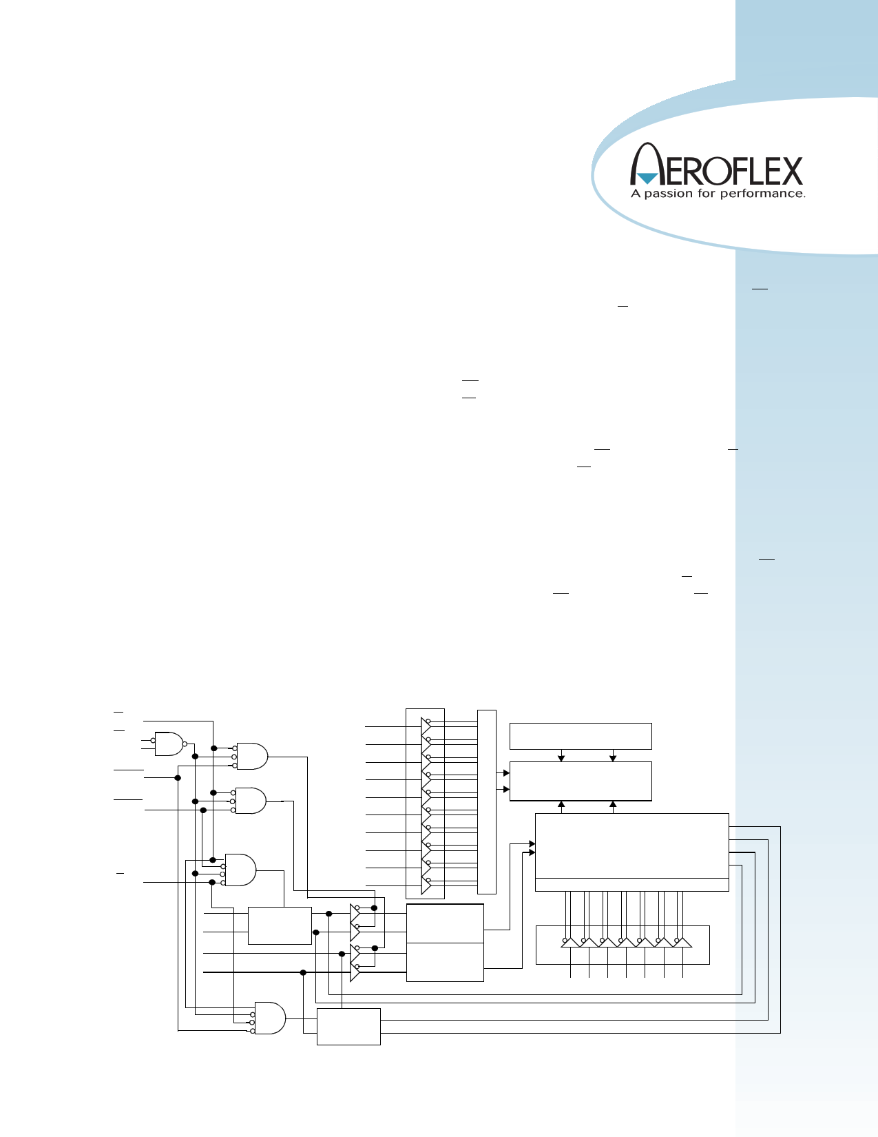
The UT8R128K32 is a high-performance CMOS static RAM
organized as 131,072 words by 32 bits. Easy memory expansion
is provided by active LOW and HIGH chip enables (E1, E2), an
active LOW output enable (G), and three-state drivers. This
device has a power-down feature that reduces power
consumption by more than 90% when deselected.
Writing to the device is accomplished by taking chip enable one
(E1) input LOW, chip enable two (E2) HIGH and write enable
(W) input LOW. Data on the 32 I/O pins (DQ0 through DQ31)
is then written into the location specified on the address pins
(A0 through A16). Reading from the device is accomplished by
taking chip enable one (E1) and output enable (G) LOW while
forcing write enable (W) and chip enable two (E2) HIGH. Under
these conditions, the contents of the memory location specified
by the address pins will appear on the I/O pins.
The 32 input/output pins (DQ0 through DQ31) are placed in a
high impedance state when the device is deselected (E1 HIGH
or E2 LOW), the outputs are disabled (G HIGH), or during a
write operation (E1 LOW, E2 HIGH and W LOW).
W
E1
E2
HHWE
LHWE
G
DQ(15) to DQ(0)
•
•
•
DQ(31) to DQ(16)
•
•
•
Low Word
Read Circuit
A0
A1
A2
A3
A4
A5
A6
A7
A8
A9
High Word
Read Circuit
Pre-Charge Circuit
Memory Array
256K x 16
Data Control
Data Control
I/O Circuit
Column Select
A10 A11 A12 A13A14 A15 A16
Figure 1. UT8R128K32 SRAM Block Diagram
1
1 page 
DC ELECTRICAL CHARACTERISTICS (Pre and Post-Radiation)*
Unless otherwise noted, Tc is per the temperature ordered
SYMBOL
PARAMETER
CONDITION
VIH High-level input voltage
VIL Low-level input voltage
VOL Low-level output voltage IOL = 8mA,VDD2 =VDD2 (min)
VOH High-level output voltage IOH = -4mA,VDD2 =VDD2 (min)
CIN1 Input capacitance
ƒ = 1MHz @ 0V
CIO1
Bidirectional I/O
capacitance
ƒ = 1MHz @ 0V
IIN Input leakage current
VIN = VDD2 and VSS
IOZ Three-state output leakage VO = VDD2 and VSS
current
VDD2 = VDD2 (max),
G = VDD2 (max)
IOS2, 3
Short-circuit output current VDD2 = VDD2 (max), VO = VDD2
VDD2 = VDD2 (max), VO = VSS
IDD1(OP1) VDD1 Supply current
operating @ 1MHz
Inputs : VIL = VSS + 0.2V,
VIH = VDD2 -0.2V , IOUT = 0
VDD2 = VDD2 (max)
VDD1 = 1.9V
VDD1 = 2.0V
IDD1(OP2) VDD1 Supply current
operating @ 66MHz
Inputs : VIL = VSS + 0.2V,
VIH = VDD2 -0.2V, IOUT = 0
VDD2 = VDD2 (max)
VDD1 = 1.9V
VDD1 = 2.0V
IDD2(OP1) VDD2 Supply current
operating @ 1MHz
Inputs : VIL = VSS + 0.2V,
VIH = VDD2 -0.2V , IOUT = 0
VDD1 = VDD1 (max),
VDD2 = VDD2 (max)
IDD2(OP2) VDD2 Supply current
operating @ 66MHZ
Inputs : VIL = VSS + 0.2V,
VIH = VDD2 -0.2V, IOUT = 0
VDD1 = VDD1 (max),
VDD2 = VDD2 (max)
MIN
.7*VDD2
.8*VDD2
MAX UNIT
V
.3*VDD2
.2*VDD2
V
V
V
12 pF
12 pF
-2 2 μA
-2 2 μA
-100 +100 mA
15 mA
18 mA
85 mA
105 mA
1 mA
12 mA
5
5 Page 
A(16:0)
E1
E2
tAVET
or tAVET
E1
E2
tETEF
tBLEF
tAVAV
tEFAX
tEFAX
LHWE / HHWE
W
D(31:0)
Q(31:0)
tWLEF
tWLQZ
APPLIED DATA
tDVEF
tEFDX
Assumptions & Notes:
1. G < VIL (max). (If G > VIH (min) then Q(31:0) will be in three-state for the entire cycle.)
2. Either E1 / E2 scenario can occur.
Figure 4b. SRAM Write Cycle 2: Enable -Chip Controlled Access
11
11 Page | ||
| Páginas | Total 22 Páginas | |
| PDF Descargar | [ Datasheet UT8R128K32.PDF ] | |
Hoja de datos destacado
| Número de pieza | Descripción | Fabricantes |
| UT8R128K32 | 128K x 32 SRAM | Aeroflex Circuit Technology |
| Número de pieza | Descripción | Fabricantes |
| SLA6805M | High Voltage 3 phase Motor Driver IC. |
Sanken |
| SDC1742 | 12- and 14-Bit Hybrid Synchro / Resolver-to-Digital Converters. |
Analog Devices |
|
DataSheet.es es una pagina web que funciona como un repositorio de manuales o hoja de datos de muchos de los productos más populares, |
| DataSheet.es | 2020 | Privacy Policy | Contacto | Buscar |