|
|
|
PDF SC9257S Data sheet ( Hoja de datos )
| Número de pieza | SC9257S | |
| Descripción | PLL FOR DIGITAL TUNING SYSTEM | |
| Fabricantes | Silan Semiconductors | |
| Logotipo | ||
Hay una vista previa y un enlace de descarga de SC9257S (archivo pdf) en la parte inferior de esta página. Total 19 Páginas | ||
|
No Preview Available !
SC9257
PLL FOR DIGITAL TUNING SYSTEM
DESCRIPTION
The SC9257 is phase-locked loop (PLL) LSIs for digital tuning
systems (DTS) with built in 2 modulus prescalers.
The LSIs are used to configure high-performance digital tuning
systems, such as radio/cassette players. They allow high-performance
AM/FM tuners to be implemented easily
DIP-20-300-2.54
FEATURES
* Available in DIP20, SOP20 packages.
* High speed programmable dividers.
SOP-20-300-1.27
— FMIN: 30 to 150 MHz ..........(with 2 modulus prescaler)
— AMIN: 0.5 to 40 MHz .......( with 2 modulus prescaler or direct
dividing )
* 16-bit programmable counter, dual parallel output phase
* Turns off FM, AM and IF amps
when Standby mode function
comparator, crystal oscillator and reference counter.
* Serial data input and interface
* Uses 3.6MHz, 4.5MHz, 7.2MHz or 10.8MHz crystal oscillators
(CE,CK,DA).
* Has 15 reference FM and AM frequencies : 0.5K, 1K, 2.5K, 3K, * Supply voltage : 4.5 to 5.5 V
3.125K, 3.90625K, 5K, 6.25K, 7.8125K, 9K, 10K, 12.5K, 25K,
50K, 100K ( When using 4.5MHz crystal)
ORDERING INFORMATION
* Has an intermediate frequency (IF) measurement counter.
* Numerous general-purpose I/O pins for such uses as peripheral
circuit control.
* Has 4 output ports that are open drain.
Device
SC9257
SC9257S
Package
DIP-20-300-2.54
SOP-20-300-1.27
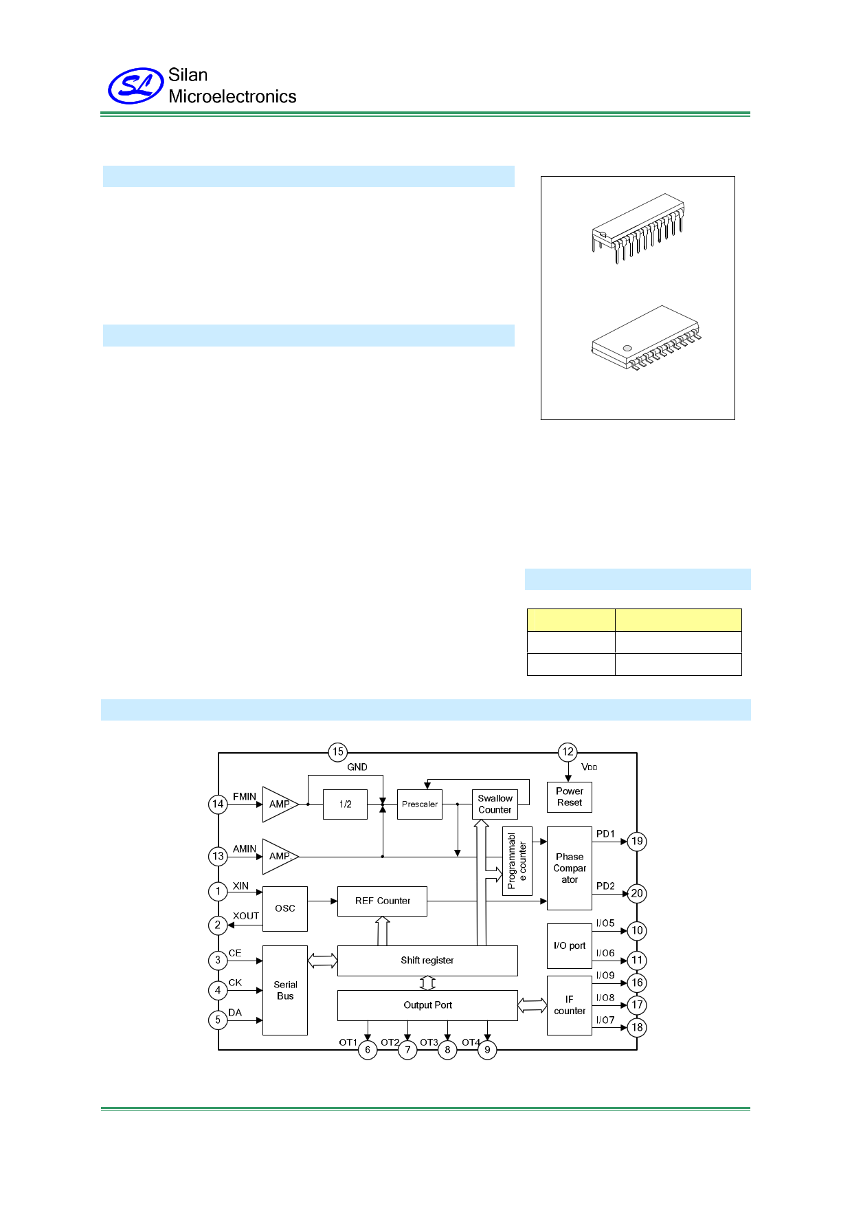
BLOCK DIAGRAM
HANGZHOU SILAN MICROELECTRONICS CO.,LTD
Http: www.silan.com.cn
REV:1.1 2005.03.28
Page 1 of 19
1 page 
SC9257
Register assignments
Address=D0H
LSB
LSB
P0 P1 P2 P3 P4 P5 P6 P7 P8 P9 P10 P11 P12 P13 P14 P15 R0 R1 R2 R3 FM MODE OSC1 OSC2
Address=D2H
Programmable counter data
(*2)
Reference
frequency
code data
Programmable
counter
mode
Crystal
oscillator
selection bits
G0 G1 SC IF1 IF2 CLK DOHZ RESET START TEST C5 C6 M7 M8 M9 O1 O2 O3 O4 O5 O6 O7 O8 O9
Gate
time
select
CLK RESET TEST
I/O port
bit
bit
bit
and general-purpose
counter switching bits
DOHZ
bit
START
bit
Also used as
general-
purpose
counter input
selection bits
I/O port control
Output port output data
Address=D1H
LSB
f0 f1 f2 f3 f4 f5 f6 f7 f8 f9 f10 f11 f12 f13 f14 f15 f16 f17 f18 f19 OVER BUSY "0" "0"
General-purpose counter data
Not
used
Address=D3H
ENA- UN
BLE LOCK
PE1
PE2
PE3
"0"
"0"
"0"
"0"
"0"
C5
C6 M7 M8 M9 O1 O2 O3 O4
I5
Lock detection data
Not used
I/O port control data
Output data
I6 I7 I8
Input data
I9
When power is turned on, the input registers are set as shown below.
Address=D0H
LSB
MSB
(*1) (*1) (*1) (*1) (*1) (*1) (*1) (*1) (*1) (*1) (*1) (*1) (*1) (*1) (*1) (*1) 1 1 1 1 1 1 0 0
Address=D2H
000000000000000000000000
Note: 1. Data are undefined.
2. Set data to “0”for test bit.
HANGZHOU SILAN MICROELECTRONICS CO.,LTD
Http: www.silan.com.cn
REV:1.1 2005.03.28
Page 5 of 19
5 Page 
SC9257
1. General-purpose output ports (OT-1~OT-4)
Pins OT-1~OT-4 are N-channel open-drain output ports, used to control signal output. They have an off
withstanding voltage of 12V. The output data of OT1~OT4 depend on the corresponding registers O1~O4
(see table 1). The data in bits O1~O4 also can be read from the DA pin as output register serial data O1~O4.
(1) O1~O4 control the output state of OT1~OT4 pins
O1~O4
0
1
PIN OUTPUT STATE
OT-1~OT-4
High impedance
(N channel open drain output =off)
"L" level
(N channel open drain output =on)
(2) The data set in bits O1~O4 of the input register can read as serial data O1~O4 from the output register.
LSB
Input register
Address D2H
O1 O2 O3 O4
MSB
LSB
Output register
Address D3H
O1 O2 O3 O4
MSB
2. General-purpose I/O ports (I/O-5~I/O-9)
Pins I/O-5~ I/O-9 are general-purpose I/O ports used for control signal input and output. They are configured
for CMOS input and output.
I/O5~ I/O9 are set by C5, C6 and M7~M9 of the input register:
When the bits C5, C6 and M7~M9 are “0”, set these ports for input; the data in these port can latch at the
output register, and as serial data read I5~I9 from DA pin.
When the bits C5, C6 and M7~M9 are “1”, set these ports for output; the data at input register O5~O9
through pin I/O-5~I/O9 output in parallel. If O5~O9 is “0”, the I/O5~I/O9 output low level in parallel; if O5~O9 is
“1”, the I/O5~I/O9 output high level in parallel.
In the SC9257, pin I/O7~I/O9 also as IF counter input pins, pin I/O5 as CLK pin, so when bits SC, IF1, IF2
and CLK are all set to “0”, above operation are valid.
Besides, bits C5, C6 and M7~M9 of the input register can be read as serial data C5, C6 and M7~M9 from
the output register.
Data which are input in parallel from pins I/O –5~I/O-9 can be read as serial data I5~I9 from the output
register (D3H)
HANGZHOU SILAN MICROELECTRONICS CO.,LTD
Http: www.silan.com.cn
REV:1.1 2005.03.28
Page 11 of 19
11 Page | ||
| Páginas | Total 19 Páginas | |
| PDF Descargar | [ Datasheet SC9257S.PDF ] | |
Hoja de datos destacado
| Número de pieza | Descripción | Fabricantes |
| SC9257 | PLL FOR DIGITAL TUNING SYSTEM | Silan Semiconductors |
| SC9257S | PLL FOR DIGITAL TUNING SYSTEM | Silan Semiconductors |
| Número de pieza | Descripción | Fabricantes |
| SLA6805M | High Voltage 3 phase Motor Driver IC. |
Sanken |
| SDC1742 | 12- and 14-Bit Hybrid Synchro / Resolver-to-Digital Converters. |
Analog Devices |
|
DataSheet.es es una pagina web que funciona como un repositorio de manuales o hoja de datos de muchos de los productos más populares, |
| DataSheet.es | 2020 | Privacy Policy | Contacto | Buscar |