|
|
|
PDF CDP1853C Data sheet ( Hoja de datos )
| Número de pieza | CDP1853C | |
| Descripción | N-Bit 1 of 8 Decoder | |
| Fabricantes | GE | |
| Logotipo | ||
Hay una vista previa y un enlace de descarga de CDP1853C (archivo pdf) en la parte inferior de esta página. Total 4 Páginas | ||
|
No Preview Available !
_ _ _ _ _ _ _ _ _ _ _ _ _ _ _ _ _ _ _ _ _ _ _ _ _ _ CMOS Peripherals
CDP1853, CDP1853C
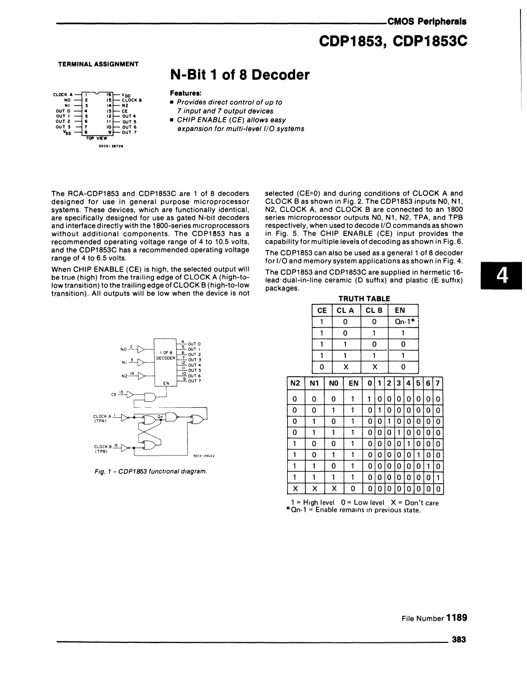
TERMINAL ASSIGNMENT
CLOCK A
NO
NI
our a
ouT I
ouT 2
OUT 3
Vss
I,..
• I.
• "12
• "10
9
TOP VIEW
Voo
CLOCK B
NC.'
OUT4
OUT'
OUT 6
our 7
N-Bit 1 of 8 Decoder
Features:
• Provides direct control of up to
7 input and 7 output devices
• CHIP ENABLE (CE) allows easy
expansion for multi-level I/O systems
The RCA-CDP1853 and CDP1853C are 1 of 8 decoders
designed for use in general purpose microprocessor
systems. These devices, which are functionally identical,
are specifically designed for use as gated N-bit decoders
and interface directly with the 1800-series microprocessors
without additional components. The CDP1853 has a
recommended operating voltage range of 4 to 10.5 volts,
and the CDP1853C has a recommended operatinQ voltage
range of 4 to 6.5 volts.
When CHIP ENABLE (CE) is high, the selected output will
be true (high) from the trailing edge of CLOCK A (high-to-
low transition) to the trailing edge of CLOCK B (high-to-Iow
transition). All outputs will be low when the device is not
.,2..(>-
N2 14
I OF 8
DECODER
"-OUT 0
5 OUT I
6 OUT 2
I~ ~~~:
II OU15
10 OUT 6
9 OUT 7
CLOCK A -'-'--f',.....=c=:::a;~1
(TPM
CLOCK B 15
(TPB) ---" /"'~-____~__~_ _ _ _- '
Fig. 1 - CDPI853 functional diagram.
selected (CE=O) and during conditions of CLOCK A and
CLOCK B as shown in Fig. 2. The CDP1853 inputs NO, Nl,
N2, CLOCK A, and CLOCK B are connected to an 1800
series microprocessor outputs NO, Nl, N2, TPA, and TPB
respectively, when used to decode I/O commands as shown
in Fig. 5. The CHIP ENABLE (CE) input provides the
capability for multiple levels of decoding as shown in Fig. 6.
The CDP1853 can also be used as a general 1 of 8 decoder
for I/O and memory system applications as shown in Fig. 4.
The CDP1853 and CDP1853C are supplied in hermetic 16-
lead'dual-in-line ceramic (0 suffiX) and plastiC (E suffiX)
packages.
TRUTH TABLE
CE CLA CL B EN
10
0 On-l*
10 1 1
11 0 0
11 1 1
0X X 0
N2 N1 NO EN 0 1 2 3 4 5 6 7
0 0 0 1 10000000
0 0 1 1 0 10 0 00 0 0
0 1 0 1 00 100000
0 1 1 1 000 10000
1 0 0 1 0000 1000
1 0 1 1 00000 100
1 1 0 1 000000 10
1 1 1 1 0000000 1
X X X 0 00000000
*1 = High level 0 = Low level X = Don't care
On-1 = Enable remains In previous state.
III
File Number 1189
_______________________________________________________________ 383
1 page | ||
| Páginas | Total 4 Páginas | |
| PDF Descargar | [ Datasheet CDP1853C.PDF ] | |
Hoja de datos destacado
| Número de pieza | Descripción | Fabricantes |
| CDP1853 | N-Bit 1 of 8 Decoder | Intersil Corporation |
| CDP1853 | N-Bit 1 of 8 Decoder | GE |
| CDP1853C | High-Reliability CMOS N-Bit 1 of 8 Decoder | Intersil Corporation |
| CDP1853C | N-Bit 1 of 8 Decoder | GE |
| Número de pieza | Descripción | Fabricantes |
| SLA6805M | High Voltage 3 phase Motor Driver IC. |
Sanken |
| SDC1742 | 12- and 14-Bit Hybrid Synchro / Resolver-to-Digital Converters. |
Analog Devices |
|
DataSheet.es es una pagina web que funciona como un repositorio de manuales o hoja de datos de muchos de los productos más populares, |
| DataSheet.es | 2020 | Privacy Policy | Contacto | Buscar |