|
|
|
PDF MLC031B Data sheet ( Hoja de datos )
| Número de pieza | MLC031B | |
| Descripción | 8-Bit I/O Type Micro-Controller | |
| Fabricantes | Megawin | |
| Logotipo | ||
Hay una vista previa y un enlace de descarga de MLC031B (archivo pdf) en la parte inferior de esta página. Total 30 Páginas | ||
|
No Preview Available !
MLC0xxB Series
8-bit I/O type micro-controller with voice function
Features
• Single chip 8-bit CPU
• Operation voltage: 2.4V to 5.5V
• Memory:
♦ ROM (shared by program and data):
1024K ~ 48KBytes
♦ Data RAM: 256 Bytes
• 24 input/output pins with wake-up function
• Two power-down modes for saving power
consumption:
♦ Sleep mode: micro-controller no
operation (main- and sub-oscillator still
oscillating)
♦ Stop mode: micro-controller no operation
(all oscillators stop oscillating)
• Two current DAC output for voice
synthesizer
• Dual-channel melody with programmable
envelope
• Programmable sample rate for
voice/melody function
• One serial input port and voltage
comparator built-in
• Three re-loadable 16-bit timers
• One watchdog timer built-in
• Oscillator
♦ Single or dual clock operation is
selected by code option
♦ Main oscillator operation at crystal or
RC mode is selected by code option
♦ Crystal/Ceramic oscillator up to 4MHz
@ 2.4V and 8MHz @ 3.6V
♦ RC oscillator up to 4MHz @ 2.4V
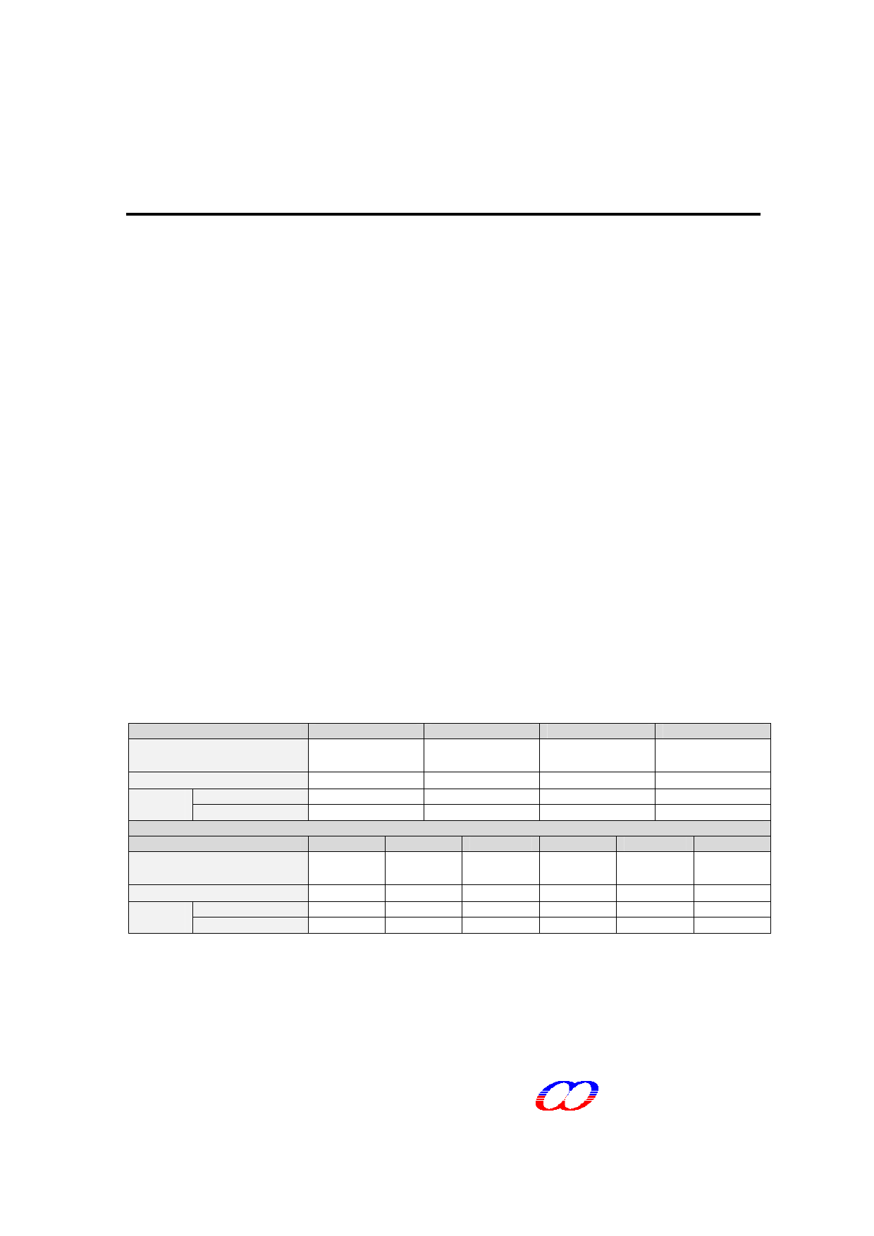
Selection Information
ROM
(Program ROM)
I/O
Voice
6KHz 4-bit ADPCM
Duration 8KHz 4-bit ADPCM
MLC331B
1024K x 8-bit
(32K x 8-bit)
24
340 sec
250 sec
MLC241B
768K x 8-bit
(32K x 8-bit)
24
250 sec
190 sec
MLS161B
512K x 8-bit
(32K x 8-bit)
24
165 sec
125 sec
MLC121B
384K x 8-bit
(32K x 8-bit)
24
125 sec
90 sec
ROM
(Program ROM)
I/O
Voice
6KHz 4-bit ADPCM
Duration 8KHz 4-bit ADPCM
MLC081B
256K x 8-bit
(32K x 8-bit)
24
80 sec
60 sec
MLC061B
192K x 8-bit
(32K x 8-bit)
24
60 sec
45 sec
MLC041B
128K x 8-bit
(32K x 8-bit)
24
40 sec
30 sec
MLC031B
96K x 8-bit
(32K x 8-bit)
24
30 sec
22 sec
MLC021B
64K x 8-bit
(32K x 8-bit)
24
20 sec
16 sec
MLC017B
48K x 8-bit
(32K x 8-bit)
24
16 sec
12 sec
This document contains information on a new product under development by MEGAWIN. MEGAWIN reserves the right to change or discontinue
this product without notice.
MEGAWIN Technology Co., Ltd. 2007 All rights reserved.
2007/05 version 0.60
MEGAWIN
1 page 
Program Counter (PC)
The 16-bit program counter register provides the addresses, which step the micro-controller through
sequential program instructions. Each time the micro-controller fetches an instruction from program
memory, the lower byte of the program counter (PCL) is placed on the low-order 8 bits of the address
bus and the higher byte of the program counter (PCH) is placed on the high-order 8 bits. The counter
is incremented each time an instruction or data is fetched from program memory.
Stack Pointer (S)
The stack pointer is an 8-bit register, which is used to control the addressing of the variable-length
stack. The stack pointer is automatically incremented and decremented under control of the
micro-controller to perform stack manipulations under direction of either the program or interrupts
(/NMI or /IRQ). The stack allows simple implementation of nested subroutines and multiple level
interrupts. The stack pointer is initialized by the user’s software.
MEGAWIN
MLC0xxB Series Technical Summary
5
5 Page 
Interrupt Registers
NMI select flag
Address
Register
00C0H
NMI_SEL
NIS2
0
0
0
0
1
1
1
1
NIS1
0
0
1
1
0
0
1
1
76
--
NIS0
0
1
0
1
0
1
0
1
5 4 3 2 1 0 RW
- - - NIS2 NIS1 NIS0 √ √
Selected NMI source
None (default)
TM0
DIV0x
P0
TM1
TM2
DIV1x
(None)
This register is used to select the NMI trigger source. The NMI is a rare resource of this system.
Only one trigger source is selected at one application is recommended. If over one trigger source is
needed in some special applications, program must to distinguish the additional interrupter. After NMI
occurs, program has to read NMI_SEL register to know which source triggering NMI.
IRQ enable flag
Address
00C2H
Name
IRQ_EN
Bit 7
-
Bit 6 Bit 5 Bit 4
- DIV1x TM2
Bit 3
TM1
Bit 2
P0
Bit 1
TM0
Program can enable or disable the ability of triggering IRQ through this register.
0: Disable (default “0” at initialization)
1: Enable
P0: Raising or falling edge occurs at port 0 input mode
TM0, TM1, TM2: Timer 0/1/2 underflow
DIV0x, DIV1x: Divider 0/1 selected interrupt frequency occurred
Bit 0 R W
DIV0x - √
IRQ status flag (same address with IRQ_EN)
Address
00C2H
Name
IRQ_ST
Bit 7
-
Bit 6 Bit 5 Bit 4
- DIV1x TM2
Bit 3
TM1
Bit 2
P0
Bit 1 Bit 0 R W
TM0 DIV0x √ -
When IRQ occurs, program can read this register to know which source triggering IRQ.
IRQ clear flag
Address
Name
Bit 7 Bit 6 Bit 5 Bit 4 Bit 3 Bit 2 Bit 1
00C3H
IRQ_CLR
-
- DIV1x TM2 TM1 P0 TM0
Program can clear the interrupt event by writing ‘1’ into the corresponding bit.
Bit 0 R W
DIV0x - √
MEGAWIN
MLC0xxB Series Technical Summary
11
11 Page | ||
| Páginas | Total 30 Páginas | |
| PDF Descargar | [ Datasheet MLC031B.PDF ] | |
Hoja de datos destacado
| Número de pieza | Descripción | Fabricantes |
| MLC031B | 8-Bit I/O Type Micro-Controller | Megawin |
| Número de pieza | Descripción | Fabricantes |
| SLA6805M | High Voltage 3 phase Motor Driver IC. |
Sanken |
| SDC1742 | 12- and 14-Bit Hybrid Synchro / Resolver-to-Digital Converters. |
Analog Devices |
|
DataSheet.es es una pagina web que funciona como un repositorio de manuales o hoja de datos de muchos de los productos más populares, |
| DataSheet.es | 2020 | Privacy Policy | Contacto | Buscar |