|
|
|
PDF UPD8259A-2 Data sheet ( Hoja de datos )
| Número de pieza | UPD8259A-2 | |
| Descripción | PROGRAMMABLE INTERRUPT CONTROLLER | |
| Fabricantes | NEC | |
| Logotipo | ||
Hay una vista previa y un enlace de descarga de UPD8259A-2 (archivo pdf) en la parte inferior de esta página. Total 18 Páginas | ||
|
No Preview Available !
NEe Microcomputers, Inc.
NEe
},PD8259A
}'PD8259A-2
PROGRAMMABLE INTERRUPT CONTROLLER
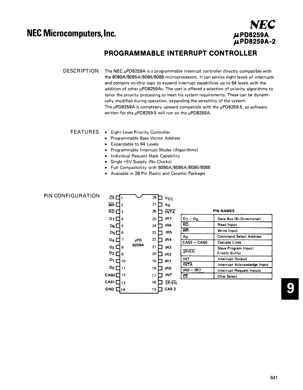
DESC RIPTI ON
The NEC J.lPD8259A is a programmable interrupt controller directly compatible with
the 8080A/8085A/8086/8088 microprocessors. It can service eight levels of interrupts
and contains on-chip logic to expand interrupt capabilities up to 64 levels with the
addition of other J.lPD8259As. The user is offered a selection of priority algorithms to
tailor the priority processing to meet his system requirements. These can be dynami-
cally modified during operation, expanding the versatility of the system.
The J.lPD8259A is completely upward compatible with the J.lPD8259-5, so software
written for the J.lPD8259-5 will run on the J.lPD8259A.
FEATU RES
• Eight Level Priority Controller
• Programmable Base Vector Address
• Expandable to 64 Levels
• Programmable Interrupt Modes (Algorithms)
• Individual Request Mask Capability
• Single +5V Supply (No Clocks)
• Full Compatibility with 8080A/8085A/8086/8088
• Available in 28 Pin Plastic and Ceramic Packages
PIN CONFIGURATION cs
WR
AD
07
Os
05
04
03
02
01
DO
CASO
CASl
GNQ
vcc
AO
iNTA
IR7
IRS
IR5
IR4
IR3
IR2
IR1
IRO
INT
SP/EN
CAS 2
07 - DO
RD
WR
AO
CAS2- CASO
SP/EN
INT
INTA
IRO-IR7
~
PIN NAMES
Data Bus (Bi-Directional)
Read Input
Write Input
Command Select Address
Cascade Lines
Slave Program Input I
Enable Buffer
Interrupt Output
Interrupt Acknowledge Input
Interrupt Request Inputs
Chip Select
641
1 page 
J'PD8259A
FUNCTIONAL
DESCRIPTION
(CONT.)
INTERRUPT ACKNOWLEDGE (lNTA)
INTA pulses cause the !.IPDB259A to put vectoring information on tile bus. The num-
ber of pulses depends upon whether the !.IPDB259A is in !.IPDBOB5A mode or BOB6/
BOBB mode.
AO
AO is usually connected to the processor's address bus. Together with WR and RD
signals it directs the loading of data into the command register or the reading of
status data. The following table illustrates the basic operations performed. Note that
it is divided into three functions: Input, Output and Bus Disable distinguished by the
RD, WR, and CS inputs.
!.IPD8259A BASIC OPERATION
AO D4 03 RD WR CS PROCESSOR INPUT OPERATION (READ)
0 0 1 0 IR R, ISR or IR ..,. Data Bus CD
1 0 1 0 IMR ..,. Data Bus
PROCESSOR OUTPUT OPERATION (WRITE)
0 0 0 1 0 0 Data Bus"" OCW2
0 0 1 1 0 0 Data Bus"" OCW3
0 1 X 1 0 0 Data Bus"" ICW1
1 X X 1 0 0 Data Bus"" OCW1, ICW2, ICW3 ~
DISABLE FUNCTION
XXX1
XXXX
1 0 Data Bus"" 3-State
X 1 Data Bus"" 3-State
<DNotes: The contents of OCW2 written prior to the READ operation governs the
selection of the I,RR, ISR or Interrupt Level.
~ The sequencer logic on the !.IPDB259A aligns these commands in the
proper order.
CASCADE BUFFER/COMPARATOR. (For Use in Multiple !.IPD8259 Array_)
The ID's of all !.IPDB259A's are buffered and compared in the cascade buffer/com-
parator. The master !.IPDB259A sends the 10 of the interrupting slave device along
the CASO, 1, 2 lines to all slave devices. The cascade buffer/comparator compares its
preprogrammed ID to the CASO, 1, 2 lines. The next two ii\f'i'A pulses strobe the pre-
programmed, 2 byte CALL routine address onto the data bus from the slave whose ID
matches the code on the CASO, 1, 2 lines.
SLAVE ~ROGRAM (SP). (For Use in Multiple !.IPD8259A Array,)
II
The interrupt capability can be expanded to 64 levels by cascading mUltiple !.IPDB259A's
in a master-plus-slaves array. The master controls the slaves through the CASO, 1, 2
lines. The SP input to the device selects the CASO-2 lines as either outputs (SP=1) for
the master or as inputs (SP=O) for the slaves. For one device only the SP must be set
to a logic "1" since it is functioning as a master.
645
5 Page 
jLPD8259A
OPPERATIONAL COMMAND
WORDS (OCW's) @
Once the !lPD8259A has been programmed with Initialization Command Words,
it can be programmed for the appropriate interrupt algorithm by the Operation
Command Words. Interrupt algorithms in the !lPD8259A can be changed at any time
during program operation by issuing another set of Operation Command Words. The
following sections describe the various algorithms available and their associated OCWs.
INTERRUPT MASKS
The individual Interrupt Request input lines are maskable by setting the corresponding
bits in the Interrupt Mask Register to a logic "1" through OCW1. The actual masking
is performed upon the contents of the In-Service Register (e.g., if Interrupt Request
line 3 is to be masked, then only bit 3 of the IMR is set to logic "1." The IMR in turn
acts upon the contents of the ISR to mask b~t 3). Once the /.lPD8259A has acknowledged
an interrupt, i.e., the !lPD8259A has sent an INT si!jnal to the processor and the system
controller has sent it an INTA signal, the interrupt inp\Jt,' ,although it is masked,
inhibits lower priority requests from being acknowledged. There are two means of
enabling these lower priority interrupt lines. The first is by issuing an End-of-Interrupt
(EO\) through Operation Command Word 2 (OCW2), thereby resetting the appro-
priate ISR bit. The second approach is to select the Special Mask Mode through OCW3.
The Special Mask Mode (SMM) and End-of-Interrupt (EO)) will be described in more
detail further on.
FUllY NESTED MODE
The fully nested mode is the !lPD8259A's basic operating mode. It will operate in this
mode after the initialization sequence, without requiring Operation Command Words
for formatting. Priorities are set IRO through IR7, with IRO the highest priority. After
the interrupt has been acknowledged by the processor and system controller, only
higher priorities will be serviced. Upon receiving an INTA, the priority resolver
determines the priority of the interrupt, sets the corresponding IR bit, and outputs the
vector address to the Data bus. The EOI command resets the corresponding ISR bits at
the end of its service routines.
CDNotes: Reference Figure 2
@ Reference Figure 3
II
651
11 Page | ||
| Páginas | Total 18 Páginas | |
| PDF Descargar | [ Datasheet UPD8259A-2.PDF ] | |
Hoja de datos destacado
| Número de pieza | Descripción | Fabricantes |
| UPD8259A-2 | PROGRAMMABLE INTERRUPT CONTROLLER | NEC |
| Número de pieza | Descripción | Fabricantes |
| SLA6805M | High Voltage 3 phase Motor Driver IC. |
Sanken |
| SDC1742 | 12- and 14-Bit Hybrid Synchro / Resolver-to-Digital Converters. |
Analog Devices |
|
DataSheet.es es una pagina web que funciona como un repositorio de manuales o hoja de datos de muchos de los productos más populares, |
| DataSheet.es | 2020 | Privacy Policy | Contacto | Buscar |