|
|
|
PDF X93156 Data sheet ( Hoja de datos )
| Número de pieza | X93156 | |
| Descripción | Single Digitally Controlled Potentiometer | |
| Fabricantes | Intersil | |
| Logotipo | ||
Hay una vista previa y un enlace de descarga de X93156 (archivo pdf) en la parte inferior de esta página. Total 7 Páginas | ||
|
No Preview Available !
NOcTN1o-ORn88tERa8CcE-tOICNoMOTuMEMr RETMSeN®EcIDLNhEnDoDirEcwaDFlODwSRSRawEuit.pPnNainpLEgStoAeWhrrlCtseeDECielEM.etDcSnEoItimNGegrT/NtiasSttcally
Controlled
November
Potentiometer
21, 2007
X93156
(XDCP™)
FN8182.3
Low Noise, Low Power, 3 wire Up/Down,
32 Taps
The Intersil X93156 is a three-terminal digitally controlled
potentiometer (XDCP). The device consists of a resistor
array, wiper switches, a control section, and nonvolatile
memory. The wiper position is controlled by an Up/Down
interface.
The potentiometer is implemented by a resistor array
composed of 31 resistive elements and a wiper switching
network. The position of the wiper element is controlled by
the CS, U/D, and INC inputs. The position of the wiper can
be stored in a nonvolatile memory and then be recalled upon
a subsequent power-up operation.
The device can be used as a three-terminal potentiometer or
as a two terminal variable resistor in a wide variety of
applications including the programming of bias voltages,
LCD brightness and contrast control as well as the
implementation of ladder networks.
Features
• Solid-state potentiometer
• Up/Down interface
• 32 wiper tap points
- Wiper position stored in nonvolatile memory and
recalled on power-up
• 31 resistive elements
- Temperature compensated
- Maximum resistance tolerance of ±25%
- Terminal voltage, 0 to VCC
• Low power CMOS
- VCC = 2.7V to 5.5V
- Active current, 200µA typ.
- Standby current, 2µA max.
• High reliability
- Endurance 200,000 data changes per bit
- Register data retention, 100 years
• RTOTAL value = 12.5k50k
• Package
- 8 Ld MSOP
- Pb-free Available (RoHS compliant)
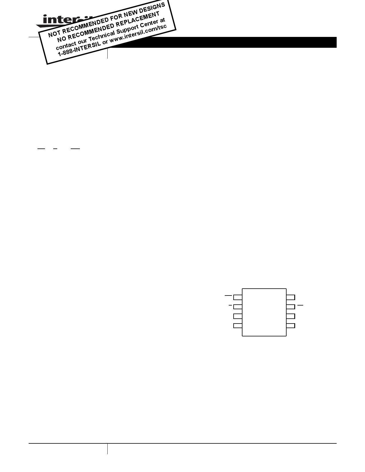
Pinout
X93156
(8 LD MSOP)
TOP VIEW
INC 1
8
U/D 2
7
RH
X93156
36
VSS 4
5
VCC
CS
RL
Rw
1
CAUTION: These devices are sensitive to electrostatic discharge; follow proper IC Handling Procedures.
1-888-INTERSIL or 1-888-468-3774 | Intersil (and design) is a registered trademark of Intersil Americas Inc.
XDCP is a trademark of Intersil Americas Inc. Copyright Intersil Americas Inc. 2005, 2007. All Rights Reserved
All other trademarks mentioned are the property of their respective owners.
1 page 
X93156
AC Electrical Specifications Over recommended operating conditions unless otherwise specified. (Continued)
SYMBOL
PARAMETER
MIN TYP MAX
tR, tF
INC input rise and fall time
(Note 7)
500
tR VCC VCC power-up rate
(Note 7)
0.2 50
tWR Store cycle
5 10
AC Timing
UNIT
µs
V/ms
ms
CS
tCI
INC
U/D
tIW
RW
tCYC
tIL
tIH
tID
tIC
tDI
tCPHS
MI (Note 4)
90% 90%
10%
tCPHNS
tF tR
Power-Up and Down Requirements
There are no restrictions on the power-up or power-down
conditions of VCC and the voltages applied to the
potentiometer pins provided that VCC is always more
positive than or equal to VH and VL, i.e., VCC VH,VL. The
VCC ramp rate spec is always in effect.
Pin Descriptions
RH and RL
The RH and RL pins of the X93156 are equivalent to the fixed
terminals of a mechanical potentiometer. The minimum
voltage is VSS and the maximum is VCC. The terminology of
RH and RL references the relative position of the terminal in
relation to wiper movement direction selected by the U/D
input.
Rw
The Rw pin of the X93156 is the wiper terminal of the
potentiometer which is equivalent to the movable terminal of
a mechanical potentiometer.
Up/Down (U/D)
The U/D input controls the direction of the wiper movement
and whether the counter is incremented or decremented.
Increment (INC)
The INC input is negative-edge triggered. Toggling INC will
move the wiper and either increment or decrement the
counter in the direction indicated by the logic level on the
U/D input.
Chip Select (CS)
The device is selected when the CS input is LOW. The
current counter value is stored in nonvolatile memory when
CS is returned HIGH while the INC input is also HIGH. After
the store operation is complete the X93156 will be placed in
the low power standby mode until the device is selected
once again.
5 FN8182.3
November 21, 2007
5 Page | ||
| Páginas | Total 7 Páginas | |
| PDF Descargar | [ Datasheet X93156.PDF ] | |
Hoja de datos destacado
| Número de pieza | Descripción | Fabricantes |
| X9315 | E 2 POT TM Nonvolatile Digital Potentiometer | Xicor |
| X9315 | Digitally Controlled Potentiometer | Intersil |
| X93154 | Low Noise Low Power 32 Taps | Intersil |
| X93155 | Digitally Controlled Potentiometer | Intersil |
| Número de pieza | Descripción | Fabricantes |
| SLA6805M | High Voltage 3 phase Motor Driver IC. |
Sanken |
| SDC1742 | 12- and 14-Bit Hybrid Synchro / Resolver-to-Digital Converters. |
Analog Devices |
|
DataSheet.es es una pagina web que funciona como un repositorio de manuales o hoja de datos de muchos de los productos más populares, |
| DataSheet.es | 2020 | Privacy Policy | Contacto | Buscar |