|
|
|
PDF MCR218-2FP Data sheet ( Hoja de datos )
| Número de pieza | MCR218-2FP | |
| Descripción | Silicon Controlled Rectifiers | |
| Fabricantes | Motorola Semiconductors | |
| Logotipo | ||
Hay una vista previa y un enlace de descarga de MCR218-2FP (archivo pdf) en la parte inferior de esta página. Total 6 Páginas | ||
|
No Preview Available !
MOTOROLA
SEMICONDUCTOR TECHNICAL DATA
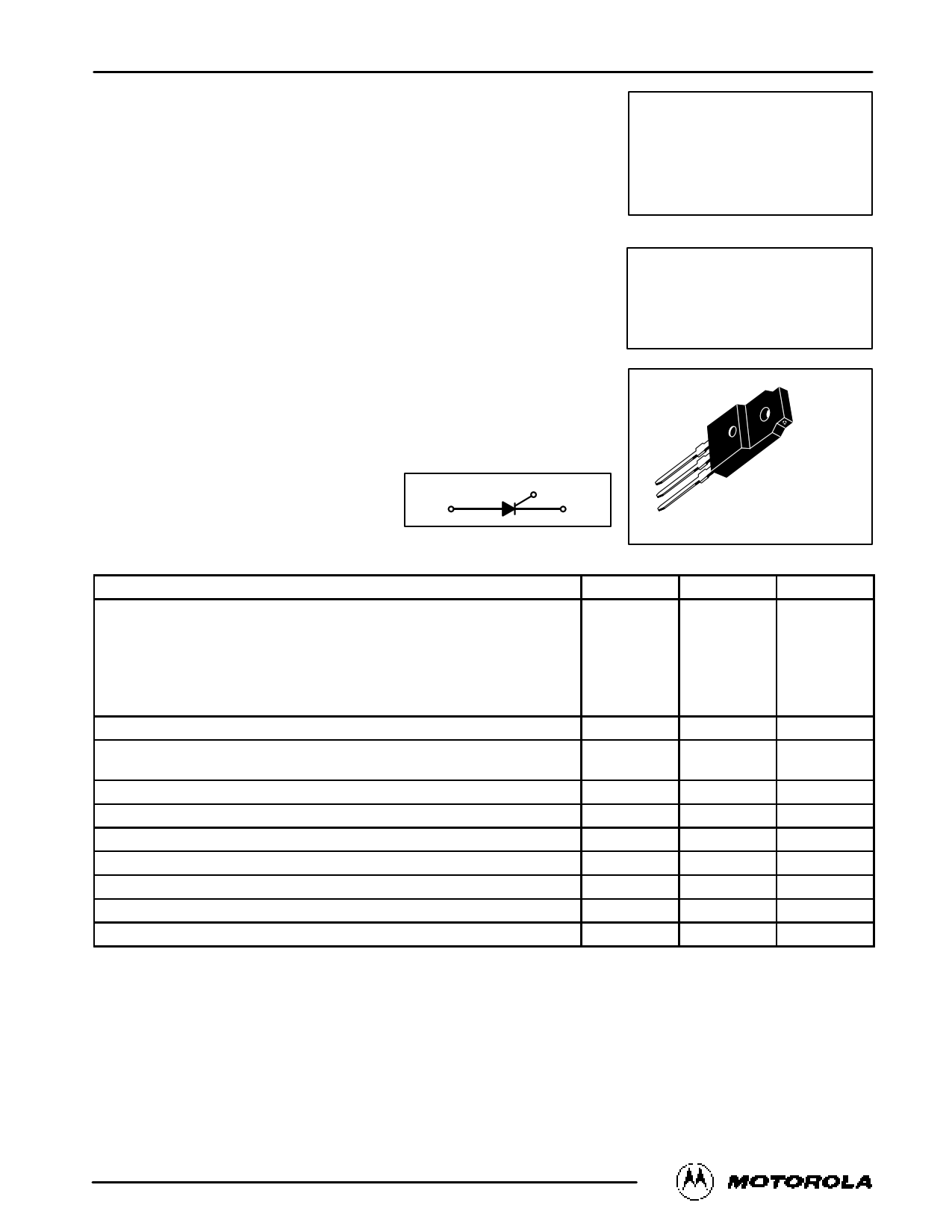
Silicon Controlled Rectifiers
Reverse Blocking Thyristors
. . . designed primarily for half-wave ac control applications, such as motor controls,
heating controls and power supply crowbar circuits.
• Glass Passivated Junctions with Center Gate Fire for Greater Parameter Uniformity
and Stability
• Small, Rugged, Thermowatt Constructed for Low Thermal Resistance, High Heat
Dissipation and Durability
• Blocking Voltage to 800 Volts
• 80 A Surge Current Capability
• Insulated Package Simplifies Mounting
Order this document
by MCR218FP/D
MCR218FP
Series
ISOLATED SCRs
8 AMPERES RMS
50 thru 800 VOLTS
G
AK
CASE 221C-02
STYLE 2
MAXIMUM RATINGS (TJ = 25°C unless otherwise noted.)
Rating
Symbol
Value
Unit
Peak Repetitive Forward and Reverse Blocking Voltage(1)
(TJ = –40 to +125°C, Gate Open)
MCR218-2FP
MCR218-4FP
MCR218-6FP
MCR218-8FP
MCR218-10FP
VDRM
VRRM
50
200
400
600
800
Volts
On-State RMS Current (TC = +70°C) Full Cycle Sine Wave 50 to 60 Hz(2)
Peak Nonrepetitive Surge Current (One Full Cycle, 60 Hz, TC = +70°C)
Preceded and followed by rated current
IT(RMS)
ITSM
8
80
Amps
Amps
Circuit Fusing (t = 8.3 ms)
I2t 26 A2s
Peak Gate Power (TC = +70°C, Pulse Width = 10 µs)
PGM 5 Watts
Average Gate Power (TC = +70°C, t = 8.3 ms)
PG(AV)
0.5
Watt
Peak Gate Current (TC = +70°C, Pulse Width = 10 µs)
pRMS Isolation Voltage (TA = 25°C, Relative Humidity 20%)
IGM
V(ISO)
2
1500
Amps
Volts
Operating Junction Temperature
TJ –40 to +125 °C
Storage Temperature Range
Tstg –40 to +125
°C
1. VDRM and VRRM for all types can be applied on a continuous basis. Ratings apply for zero or negative gate voltage; however, positive gate
voltage shall not be applied concurrent with negative potential on the anode. Blocking voltages shall not be tested with a constant current
source such that the voltage ratings of the devices are exceeded.
2. The case temperature reference point for all TC measurements is a point on the center lead of the package as close as possible to the plastic body.
Motorola Thyristor Device Data
© Motorola, Inc. 1995
1
1 page 
PACKAGE DIMENSIONS
MCR218FP Series
–B–
P
–T–
SEATING
PLANE
FC
S
N
H
–Y–
Q
Z
G
1 23
A
E
K
LJ
D 3 PL
0.25 (0.010) M B M Y
R
STYLE 2:
PIN 1.
2.
3.
CATHODE
ANODE
GATE
NOTES:
1. DIMENSIONING AND TOLERANCING PER ANSI
Y14.5M, 1982.
2. CONTROLLING DIMENSION: INCH.
3. LEAD DIMENSIONS UNCONTROLLED WITHIN
DIMENSION Z.
INCHES
DIM MIN MAX
A 0.680 0.700
B 0.388 0.408
C 0.175 0.195
D 0.025 0.040
E 0.340 0.355
F 0.140 0.150
G 0.100 BSC
H 0.110 0.155
J 0.018 0.028
K 0.500 0.550
L 0.045 0.070
N 0.049 –––
P 0.270 0.290
Q 0.480 0.500
R 0.090 0.120
S 0.105 0.115
Z 0.070 0.090
MILLIMETERS
MIN MAX
17.28 17.78
9.86 10.36
4.45 4.95
0.64 1.01
8.64 9.01
3.56 3.81
2.54 BSC
2.80 3.93
0.46 0.71
12.70 13.97
1.15 1.77
1.25 –––
6.86 7.36
12.20 12.70
2.29 3.04
2.67 2.92
1.78 2.28
CASE 221C-02
Motorola Thyristor Device Data
5
5 Page | ||
| Páginas | Total 6 Páginas | |
| PDF Descargar | [ Datasheet MCR218-2FP.PDF ] | |
Hoja de datos destacado
| Número de pieza | Descripción | Fabricantes |
| MCR218-2FP | Silicon Controlled Rectifiers | Motorola Semiconductors |
| Número de pieza | Descripción | Fabricantes |
| SLA6805M | High Voltage 3 phase Motor Driver IC. |
Sanken |
| SDC1742 | 12- and 14-Bit Hybrid Synchro / Resolver-to-Digital Converters. |
Analog Devices |
|
DataSheet.es es una pagina web que funciona como un repositorio de manuales o hoja de datos de muchos de los productos más populares, |
| DataSheet.es | 2020 | Privacy Policy | Contacto | Buscar |