|
|
|
PDF AT24C01 Data sheet ( Hoja de datos )
| Número de pieza | AT24C01 | |
| Descripción | 2-Wire Serial EEPROM | |
| Fabricantes | ATMEL Corporation | |
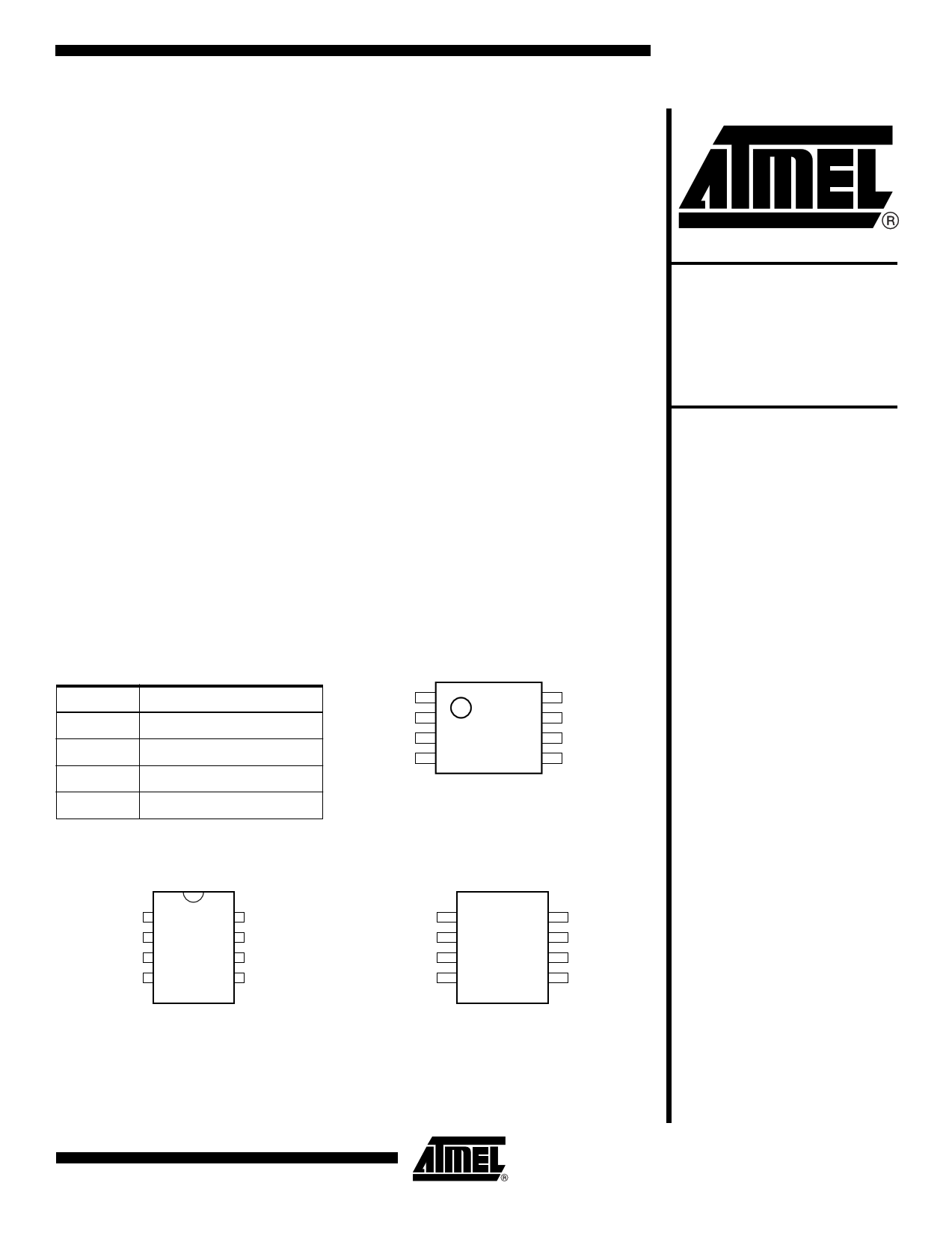
| Logotipo | ||
Hay una vista previa y un enlace de descarga de AT24C01 (archivo pdf) en la parte inferior de esta página. Total 14 Páginas | ||
|
No Preview Available !
Features
• Low Voltage and Standard Voltage Operation
– 2.7 (VCC = 2.7V to 5.5V)
– 1.8 (VCC = 1.8V to 5.5V)
• Internally Organized 128 x 8
• 2-Wire Serial Interface
• Bidirectional Data Transfer Protocol
• 100 kHz (1.8V, 2.5V, 2.7V) and 400 kHz (5V) Compatibility
• 4-Byte Page Write Mode
• Self-Timed Write Cycle (10 ms max)
• High Reliability
– Endurance: 1 Million Write Cycles
– Data Retention: 100 Years
• Automotive Grade, Extended Temperature and Lead-Free Devices Available
• 8-lead PDIP, 8-lead JEDEC SOIC and 8-lead TSSOP Packages
Description
The AT24C01 provides 1024 bits of serial electrically erasable and programmable
read only memory (EEPROM) organized as 128 words of 8 bits each. The device is
optimized for use in many industrial and commercial applications where low power
and low voltage operation are essential. The AT24C01 is available in space saving
8-lead PDIP, 8-lead JEDEC SOIC and 8-lead TSSOP packages and is accessed via a
2-wire serial interface. In addition, the entire family is available in 2.7V (2.7V to 5.5V)
and 1.8V (1.8V to 5.5V) versions.
2-Wire Serial
EEPROM
1K (128 x 8)
AT24C01
Pin Configurations
Pin Name
NC
SDA
SCL
TEST
Function
No Connect
Serial Data
Serial Clock Input
Test Input (GND or VCC)
8-lead PDIP
NC
NC
NC
GND
1
2
3
4
8 VCC
7 TEST
6 SCL
5 SDA
NC
NC
NC
GND
8-lead TSSOP
18
27
36
45
VCC
TEST
SCL
SDA
8-lead SOIC
NC
NC
NC
GND
1
2
3
4
8 VCC
7 TEST
6 SCL
5 SDA
Rev. 0134G–SEEPR–7/03
1
1 page 
Device Operation
AT24C01
CLOCK and DATA TRANSITIONS: The SDA pin is normally pulled high with an exter-
nal device. Data on the SDA pin may change only during SCL low time periods (refer to
Data Validity timing diagram). Data changes during SCL high periods will indicate a start
or stop condition as defined below.
START CONDITION: A high-to-low transition of SDA with SCL high is a start condition
which must precede any other command (refer to Start and Stop Definition timing
diagram).
STOP CONDITION: A low-to-high transition of SDA with SCL high is a stop condition
which terminates all communications. After a read sequence, the stop command will
place the EEPROM in a standby power mode (refer to Start and Stop Definition timing
diagram).
ACKNOWLEDGE: All addresses and data words are serially transmitted to and from
the EEPROM in 8-bit words. Any device on the system bus receiving data (when com-
municating with the EEPROM) must pull the SDA bus low to acknowledge that it has
successfully received each word. This must happen during the ninth clock cycle after
each word received and after all other system devices have freed the SDA bus. The
EEPROM will likewise acknowledge by pulling SDA low after receiving each address or
data word (refer to Acknowledge Response from Receiver timing diagram).
STANDBY MODE: The AT24C01 features a low power standby mode which is enabled:
(a) upon power-up and (b) after the receipt of the STOP bit and the completion of any
internal operations.
MEMORY RESET: After an interruption in protocol, power loss or system reset, any 2-
wire part can be reset by following these steps:
(a) Clock up to 9 cycles, (b) look for SDA high in each cycle while SCL is high and then
(c) create a start condition as SDA is high.
0134G–SEEPR–7/03
5
5 Page 
Packaging Information
8P3 – PDIP
1
AT24C01
E
E1
N
Top View
c
eA
End View
D
e
D1 A2 A
b3
4 PLCS
b2
b
Side View
L
COMMON DIMENSIONS
(Unit of Measure = inches)
SYMBOL
A
A2
b
b2
b3
c
D
D1
E
E1
e
eA
L
MIN NOM MAX
0.210
0.115 0.130 0.195
0.014 0.018 0.022
0.045 0.060 0.070
0.030 0.039 0.045
0.008 0.010 0.014
0.355 0.365 0.400
0.005
0.300 0.310 0.325
0.240 0.250 0.280
0.100 BSC
0.300 BSC
0.115 0.130 0.150
NOTE
2
5
6
6
3
3
4
3
4
2
Notes:
1. This drawing is for general information only; refer to JEDEC Drawing MS-001, Variation BA for additional information.
2. Dimensions A and L are measured with the package seated in JEDEC seating plane Gauge GS-3.
3. D, D1 and E1 dimensions do not include mold Flash or protrusions. Mold Flash or protrusions shall not exceed 0.010 inch.
4. E and eA measured with the leads constrained to be perpendicular to datum.
5. Pointed or rounded lead tips are preferred to ease insertion.
6. b2 and b3 maximum dimensions do not include Dambar protrusions. Dambar protrusions shall not exceed 0.010 (0.25 mm).
01/09/02
2325 Orchard Parkway
R San Jose, CA 95131
TITLE
8P3, 8-lead, 0.300" Wide Body, Plastic Dual
In-line Package (PDIP)
DRAWING NO. REV.
8P3 B
0134G–SEEPR–7/03
11
11 Page | ||
| Páginas | Total 14 Páginas | |
| PDF Descargar | [ Datasheet AT24C01.PDF ] | |
Hoja de datos destacado
| Número de pieza | Descripción | Fabricantes |
| AT24C01 | 2-Wire Serial EEPROM | ATMEL Corporation |
| AT24C01A | 2-Wire Serial EEPROM | ATMEL Corporation |
| AT24C01B | 2-Wire Automotive Temperature Serial EEPROM | ATMEL Corporation |
| AT24C01C | EEPROM | ATMEL Corporation |
| Número de pieza | Descripción | Fabricantes |
| SLA6805M | High Voltage 3 phase Motor Driver IC. |
Sanken |
| SDC1742 | 12- and 14-Bit Hybrid Synchro / Resolver-to-Digital Converters. |
Analog Devices |
|
DataSheet.es es una pagina web que funciona como un repositorio de manuales o hoja de datos de muchos de los productos más populares, |
| DataSheet.es | 2020 | Privacy Policy | Contacto | Buscar |