|
|
|
PDF HS-1825ARH Data sheet ( Hoja de datos )
| Número de pieza | HS-1825ARH | |
| Descripción | Radiation Hardened High-Speed Dual Output PWM | |
| Fabricantes | Intersil Corporation | |
| Logotipo | ||
Hay una vista previa y un enlace de descarga de HS-1825ARH (archivo pdf) en la parte inferior de esta página. Total 6 Páginas | ||
|
No Preview Available !
DATASHEET
Radiation Hardened High-Speed, Dual Output PWM
HS-1825ARH, HS-1825AEH
The radiation hardened HS-1825ARH, HS-1825AEH pulse
width modulator is designed to be used in high frequency
switched-mode power supplies and can be used in either
current-mode or voltage-mode. It is well suited for single-ended
boost converter applications.
Device features include a precision voltage reference, low
power start-up circuit, high frequency oscillator, wide-band
error amplifier and fast current-limit comparator. The use of
proprietary process capabilities and unique design techniques
results in fast propagation delay times and high output current
over a wide range of output voltages.
Constructed with the Intersil radiation hardened Silicon Gate
(RSG) Dielectric Isolation BiCMOS process, the HS-1825ARH,
HS-1825AEH have been specifically designed to provide highly
reliable performance when exposed to harsh radiation
environments.
Features
• Electrically screened to DLA SMD # 5962-99558
• QML qualified per MIL-PRF-38535 Requirements
• Radiation environment
- Maximum total dose . . . . . . . . . . . . . . . . . . . . 300 krad(SI)
- Vertical architecture provides low dose rate immunity
- DI RSG process provides latch-up immunity
• Low start-up current. . . . . . . . . . . . . . . . . . . . . 100µA (Typical)
• Fast propagation delay . . . . . . . . . . . . . . . . . . . . 80ns (Typical)
• 12V to 30V operation
• 1A (peak) dual output drive capability
• 5.1V reference
• Undervoltage lockout
• Programmable soft-start
• Switching frequencies to 500kHz
• Latched overcurrent comparator with full cycle restart
• Programmable leading edge blanking circuit
Applications
• Current or voltage mode switching power supplies
• Motor speed and direction control
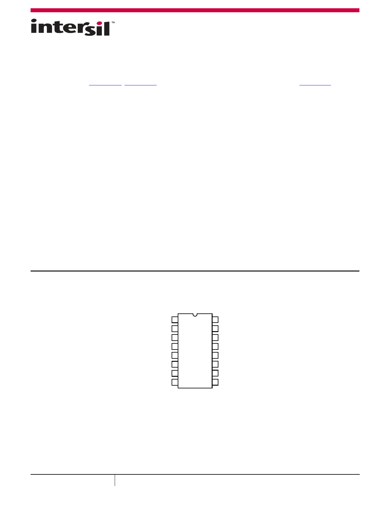
Pin Configuration
HS-1825ARH, HS-1825AEH
SBDIP (CDIP2-T16) AND FLATPACK (CDFP4-F16)
TOP VIEW
INV 1
NON-INV 2
E/A OUT 3
CLOCK 4
RT 5
CT 6
RAMP 7
SOFT START 8
16 VREF 5.1V
15 VCC
14 OUTPUT B
13 VC
12 POWER GND
11 OUTPUT A
10 GND
9 ILIM/SD
NOTE: Grounding the soft-start pin does not inhibit the outputs. The outputs may be inhibited by applying >1.26V to the ILIM/SD pin.
August 5, 2016
FN4561.10
1 CAUTION: These devices are sensitive to electrostatic discharge; follow proper IC Handling Procedures.
1-888-INTERSIL or 1-888-468-3774 | Copyright Intersil Americas LLC 2002, 2005, 2008, 2012, 2016. All Rights Reserved
Intersil (and design) is a trademark owned by Intersil Corporation or one of its subsidiaries.
All other trademarks mentioned are the property of their respective owners.
1 page 
HS-1825ARH, HS-1825AEH
Ceramic Dual-In-Line Metal Seal Packages (SBDIP)
-A- -D-
E
-B-
bbb S C A - B S D S
c1 LEAD FINISH
BASE
METAL
(c)
b1
MM
(b)
SECTION A-A
BASE
PLANE
SEATING
PLANE
D
S1
b2
b
AA
e
ccc M C A - B S D S
S2 Q
-C- A
L
eA
eA/2
c
aaa M C A - B S D S
NOTES:
1. Index area: A notch or a pin one identification mark shall be locat-
ed adjacent to pin one and shall be located within the shaded
area shown. The manufacturer’s identification shall not be used
as a pin one identification mark.
2. The maximum limits of lead dimensions b and c or M shall be
measured at the centroid of the finished lead surfaces, when
solder dip or tin plate lead finish is applied.
3. Dimensions b1 and c1 apply to lead base metal only. Dimension
M applies to lead plating and finish thickness.
4. Corner leads (1, N, N/2, and N/2+1) may be configured with a
partial lead paddle. For this configuration dimension b3 replaces
dimension b2.
5. Dimension Q shall be measured from the seating plane to the
base plane.
6. Measure dimension S1 at all four corners.
7. Measure dimension S2 from the top of the ceramic body to the
nearest metallization or lead.
8. N is the maximum number of terminal positions.
9. Braze fillets shall be concave.
10. Dimensioning and tolerancing per ANSI Y14.5M - 1982.
11. Controlling dimension: INCH.
D16.3 MIL-STD-1835 CDIP2-T16 (D-2, CONFIGURATION C)
16 LEAD CERAMIC DUAL-IN-LINE METAL SEAL PACKAGE
INCHES
MILLIMETERS
SYMBOL MIN MAX MIN MAX NOTES
A
- 0.200 - 5.08
-
b
0.014
0.026
0.36
0.66
2
b1
0.014
0.023
0.36
0.58
3
b2
0.045
0.065
1.14
1.65
-
b3
0.023
0.045
0.58
1.14
4
c
0.008
0.018
0.20
0.46
2
c1
0.008
0.015
0.20
0.38
3
D
- 0.840 - 21.34
-
E
0.220
0.310
5.59
7.87
-
e 0.100 BSC
2.54 BSC
-
eA 0.300 BSC
7.62 BSC
-
eA/2
0.150 BSC
3.81 BSC
-
L
0.125
0.200
3.18
5.08
-
Q
0.015
0.060
0.38
1.52
5
S1 0.005 - 0.13 - 6
S2 0.005 - 0.13 - 7
90o 105o 90o 105o
-
aaa
- 0.015 - 0.38
-
bbb
- 0.030 - 0.76
-
ccc
- 0.010 - 0.25
-
M
-
0.0015
-
0.038
2
N 16
16 8
Rev. 0 4/94
Submit Document Feedback
5
FN4561.10
August 5, 2016
5 Page | ||
| Páginas | Total 6 Páginas | |
| PDF Descargar | [ Datasheet HS-1825ARH.PDF ] | |
Hoja de datos destacado
| Número de pieza | Descripción | Fabricantes |
| HS-1825ARH | Radiation Hardened High-Speed Dual Output PWM | Intersil Corporation |
| Número de pieza | Descripción | Fabricantes |
| SLA6805M | High Voltage 3 phase Motor Driver IC. |
Sanken |
| SDC1742 | 12- and 14-Bit Hybrid Synchro / Resolver-to-Digital Converters. |
Analog Devices |
|
DataSheet.es es una pagina web que funciona como un repositorio de manuales o hoja de datos de muchos de los productos más populares, |
| DataSheet.es | 2020 | Privacy Policy | Contacto | Buscar |