|
|
|
PDF EX60T-C71S Data sheet ( Hoja de datos )
| Número de pieza | EX60T-C71S | |
| Descripción | High-Speed Differential Signal Connectors | |
| Fabricantes | Hirose Electric | |
| Logotipo | ||
Hay una vista previa y un enlace de descarga de EX60T-C71S (archivo pdf) en la parte inferior de esta página. Total 12 Páginas | ||
|
No Preview Available !
NEW
High-Speed Differential Signal Connectors
EXT Series
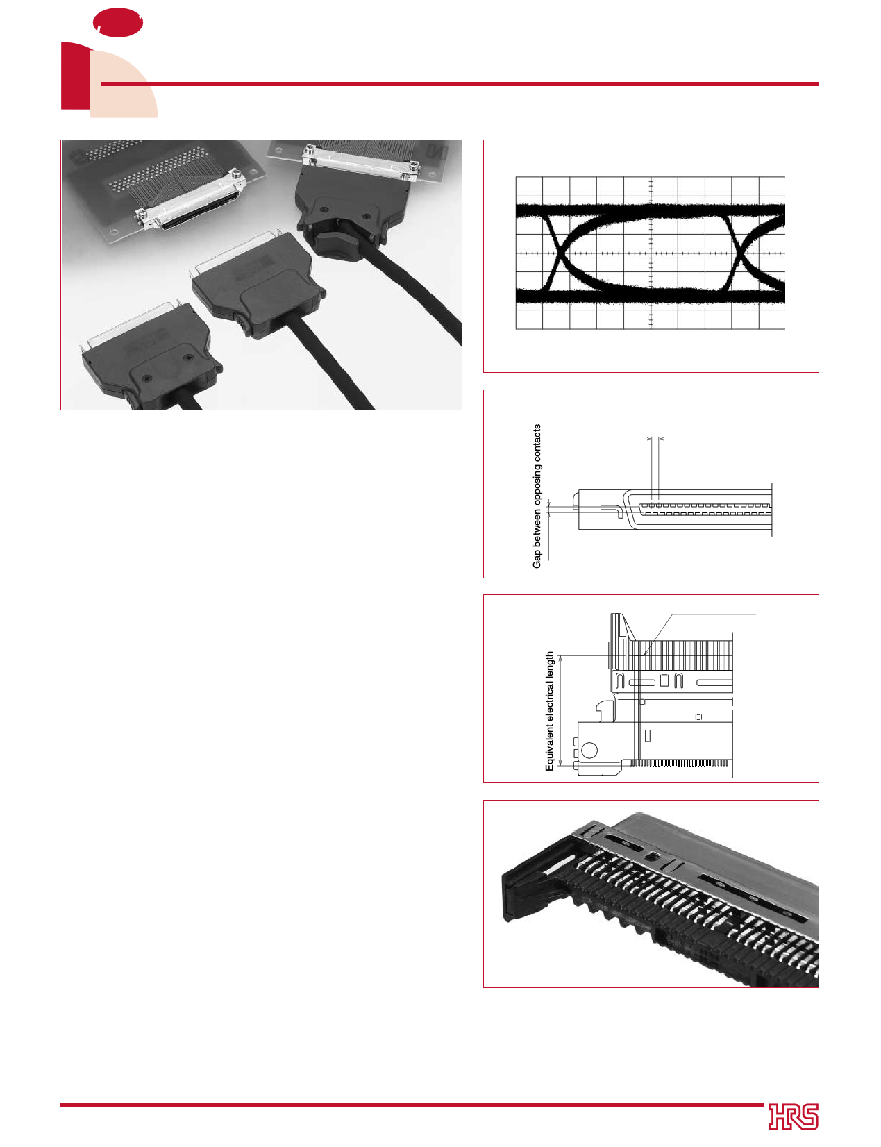
1 Gbps Eye Pattern Waveform
(One End of Connector: 2 m of AWG #28 Twinax Cable)
sFeatures
01. High-Speed Differential Signals
The construction supports high-speed differential signals
such as LVDS, IEEE 1394, and USB 2.0. Use of twisted pair
cable or twinax cable permits transmission speeds up to
several hundred Mbps and higher per twisted pair.
(A) Impedance Matching
The connector is designed to minimize reflections with a
differential impedance of 100 ohms between adjacent contacts.
(B) Low Skew Construction
An equivalent electrical length is maintained between
adjacent contacts while the equivalent electrical length
between opposing terminals is approximately zero.
Consequently the skew within differential pairs as well as
between differential pairs is approximately zero.
However, a low skew between differential pairs is permitted
by going through another layer of the board.
(C) Low Crosstalk
The design features a staggered arrangement between
opposing contacts for low crosstalk effects between opposing
pairs even though these are low-profile connectors.
Differential impedance
between adjacent
contacts is 100 ohms
Adjacent contacts
;;;;;;;;;;;;;;;;;;;;;;;;;;;;;;;;;;;;;;;;;;;;;;;;;;;;;;;;;;;;;;;;;;
02. Batch Wiring of Cables Using Solder Paste
Soldered wiring has been used as the wiring method for the
plug side composite cable, thin cable, and drain wires;
however, paste soldering permits the batch wiring of
prepared cables. (Existing soldering methods can also be
used to wire the connectors.)
03. No Shrink Tubing Required
The wiring portion of the plug side is secured by the
molding which prevents short circuits without the use of
shrink tubing. Since shrink tubing is not used, this
allows the twist back length of the twisted pair cable or
the twinax cable to be shortened, thereby permitting the
impedance of the wiring section to be kept in check.
04. Power and Signal Contacts
The 65 position connector is designed with 59 signal contacts and 6 power contacts. Each power contact is
rated for 2 Amps. The 71 position connector is supplied with signal contacts only.
05. Low-Profile Design
With the trend toward lower profiles, the receptacle is made to drop into the board, which results in a height
dimension, including the board, of 5.6mm.
2001.6
1
1 page 
sReceptacle
q65 contact (59 signal contacts, 6 power supply contacts)
EX60T-C65P (CL232-0588-5)
39.2
36
1.5
P= 0.5
50.6
54.6
56.2
Power supply contacts (six)
Board SMT surface
BBoard Mounting Diagram (for Reference)
Establishing the discardable portion of the board indicated by the shaded area of the diagram below, serves to prevent the
board from falling forward at the time of reflow. Making a V-shaped cut in the discardable portion of the board allows access to
the connector by bending and breaking off this portion after reflow.
Ø1.25 (Hole)
4-1.7x1.7
45.2
40.6
36
P= 0.5
1.65x1.25 (Elliptical hole)
Ø3 (Hole)
20.3
0.35
V-shape cut;;;;;;;;;;;;;;;;;;;;;;;;;;;;;;;;;;;;;;;;;;;;;;;;;;;;;;;;;;;;;;;;;;;;;;;;;;;;;;;;;;;;;;;;;;;;;;;;;;;;;;;;;;;;;;;;;;;;;;;;;;;;;;;;;;;;;;;;;;;;;;;;;;;;;;;;;;;;;;;;;;;;;;;;;;;;;;;;;;;;;;;;;;;;;;;;;;;;;;;;;;;;;;;;;;;;;;;;;;;;;;;;;;;;;;;;;;;;;;;;;;;;;;;;;;;;;;;;;;;;;;;;;;;;;;;;;;;;;;;;;;;;;;;;;;;;;;;;;;;;;;;;;;;;;;;;;;;;;;;;;;;;;;;;;;;;;;;;;;;;;;;;;;;;;;;;;;;;;;;;;;;;;;;;;;;;;;;;;;;;;;;;;;;;;;;;;;;;;;;;;;;;;;;;;;;;;;;;;;;;;;;;;;;;;;;;;;;;;;;;;;;;;;;;;;;;;;;;;;;;;;;;;;;;;;;;;;;;;;;;;;;;;;;;;;;;;;;;;;;;;;;;;;;;;;;;;;;;;;;;;;;;;;;;;;;;;;;;;;;;;;;;;;;;;;;;;;;;;;;;;;;;;;;;;;;;;;;;;;;;;;;;;;;;;;;;;;;;;;;;;;;;;;;;;;;;;;;;;;;;;;;;;;;;;;;;;;;;;;;;;;;;;;;;;;;;;;;;;;;;;;;;;;;;;;;;;;;;;;;;;;;;;;;;;;;;;;;;;;;;;;;;;;;;;;;;;;;;;;;;;;;;;;;;;;;;;;;;;;;;;;;;;;;;;;;;;;;;;;;;;;;;;;;;;;;;;;;;;;;;;;;;;;;;;;;;;;;;;;;;;;;;;;;;;;;;;;;;;;;;;;;;;;;;;;;;;;;;;;;;;;;;;;;;;;;;;;;;;;;;;;;;;;;;;;;;;;;;;;;;;;;;;;;;;;;;;;;;;;;;;;;;;;;;;;;;;;;;;;;;;;;;;;;;;;;;;;;;;;;;;;;;;;;;;;;;;;;;;;;;;;;;;;;;;;;;;;;;;;;;;;;;;;;;;;;;;;;;;;;;;;;;;;;;;;;;;;;;;;;;;;;;;;;;;;;;;;;;;;;;;;;;;;;;;;;;;;;;;;;;;;;;;;;;;;;;;;;;;;;;;;;;;;;;;;;;;;;;;;;;;;;;;;;;;;;;;;;;;;;;;;;;;;;;;;;;;;;;;;;;;;;;;;;;;;;;;;;;;;;;;;;;;;;;;;;;;;;;;;;;;;;;;;;;;;;;;;;;;;;;;;;;;;;;;;;;;;;;;;;;;;;;;;;;;;;;;;;;;;;;;;;;;;;;;;;;;;;;;;;;;;;;;;;;;;;;;;;;;;;;;;;;;;;;;;;;;;;;;;;;;;;;;;;;;;;;;;;;;;;;;;;;;;;;;;;;;;;;;;;;;;;;;;;;;;;;;;;;;;;;;;;;;;;;;;;;;;;;;;;;;;;;;;;;;;;;;;;;;;;;;;;;;;;;;;;;;;;;;;;;;;;;;;;;;;;;;;;;;;;;;;;;;;;;;;;;;;;;;;;;;;;;;;;;;;;;
44.8
50.6
55.4
57
5
5 Page 
qAnchoring to the Case
Mounting of the receptacle connectors makes use of screws to fasten the connectors to the case as illustrated in the
diagram below. This contributes to a structure that is resistant to twisting.
Embedded nut
;;;;;;;;;;;;;;;;;;;;;;;;;;;;;;;;;;;;;;;;;;;;;;;;;;;;;;;;;;;;;;;;;;;;;;;;;;;;;;;;;;;;;;;;;;;;;;;;;;; ;;;;;;;;;;;;;;;;;;;;;;;;;;;;;;;;;;;;;;;;;;;;;;;;;;;;;;;;;;;;;;;;;;;;;;;;;;;;;;;;;;;;;;;;;;;;;;;;;;;;;;;;;;
Case
EX60T-71P
M2 countersunk screw PCB
qA Design that Doesn't Use Heat-Shrink Tubing
The soldered wiring portion of the plug connector is secured to the molding which serves as a measure against the
short-circuiting of adjacent contacts. This eliminates the need to attach heat-shrink tubing.
The plug connector has been furnished with a retaining plate made of resin material for the purpose of preventing
short circuits with the metal portions of the cover case.
Molding
Contact
;;;;;;;;;;;;;;
Insulating retaining plate
;;;;;;;
qBatch Wiring of Plug Connectors
These connectors permit the batch soldered wiring of cables prepared with paste solder and partial reflow.
(Regularly soldered wiring is used for power supply contacts.)
Please contact our Technical Department about harness details for the purpose of satisfying harness qualities and
high-speed transmission characteristics.
11
11 Page | ||
| Páginas | Total 12 Páginas | |
| PDF Descargar | [ Datasheet EX60T-C71S.PDF ] | |
Hoja de datos destacado
| Número de pieza | Descripción | Fabricantes |
| EX60T-C71P | High-Speed Differential Signal Connectors | Hirose Electric |
| EX60T-C71PR | High-Speed Differential Signal Connectors | Hirose Electric |
| EX60T-C71S | High-Speed Differential Signal Connectors | Hirose Electric |
| EX60T-C71SR | High-Speed Differential Signal Connectors | Hirose Electric |
| Número de pieza | Descripción | Fabricantes |
| SLA6805M | High Voltage 3 phase Motor Driver IC. |
Sanken |
| SDC1742 | 12- and 14-Bit Hybrid Synchro / Resolver-to-Digital Converters. |
Analog Devices |
|
DataSheet.es es una pagina web que funciona como un repositorio de manuales o hoja de datos de muchos de los productos más populares, |
| DataSheet.es | 2020 | Privacy Policy | Contacto | Buscar |