|
|
|
PDF ATS660LSB Data sheet ( Hoja de datos )
| Número de pieza | ATS660LSB | |
| Descripción | TRUE ZERO-SPEED/ HALL-EFFECT ADAPTIVE GEAR-TOOTH SENSOR | |
| Fabricantes | Allegro MicroSystems | |
| Logotipo | ||
Hay una vista previa y un enlace de descarga de ATS660LSB (archivo pdf) en la parte inferior de esta página. Total 16 Páginas | ||
|
No Preview Available !
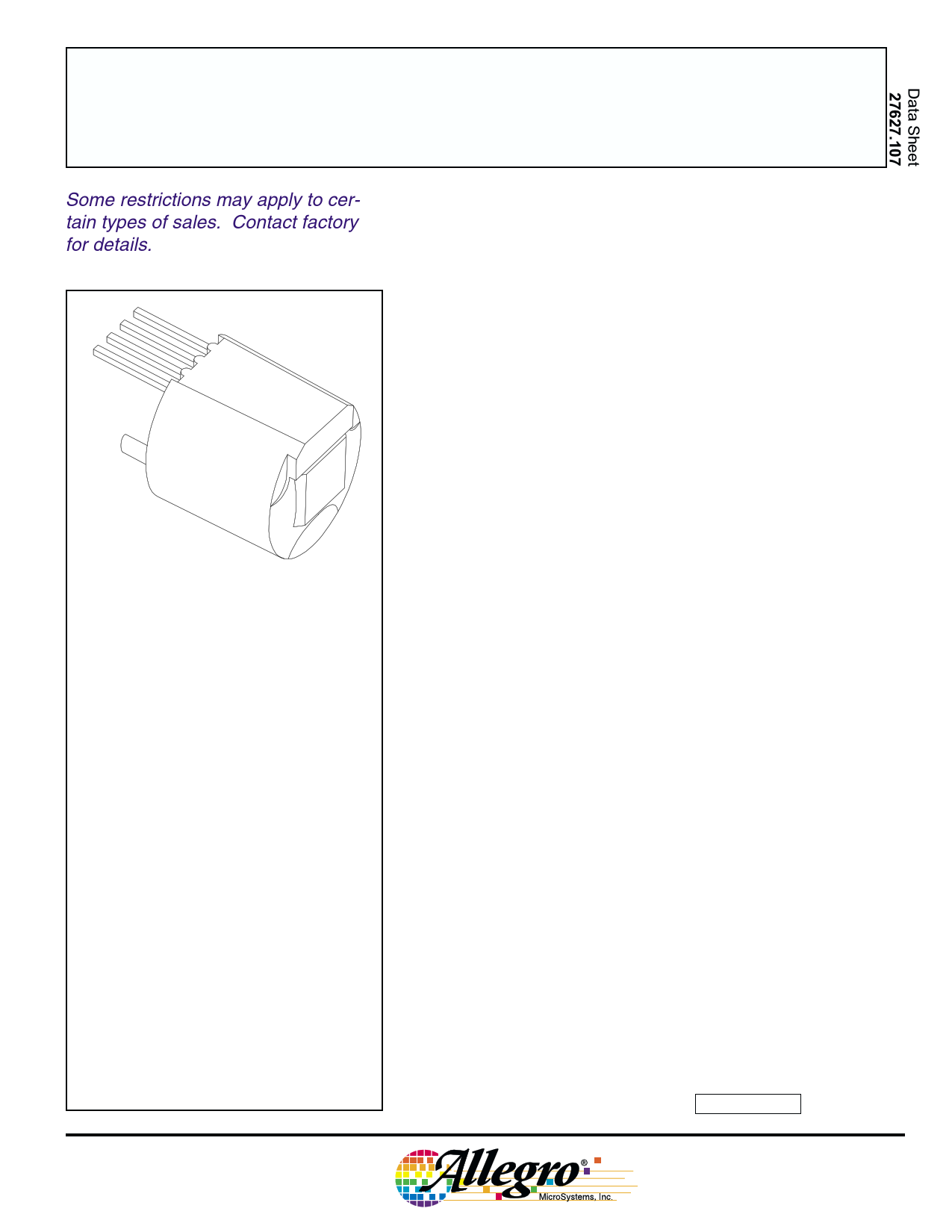
ATS660LSB
Some restrictions may apply to cer-
tain types of sales. Contact factory
for details.
TRUE ZERO-SPEED, HALL-EFFECT
ADAPTIVE GEAR-TOOTH SENSOR
1
2
3
4
Pin 1 = Supply
Pin 2 = Output
Pin 3 = Internal Connection
Pin 4 = Ground
Dwg. AH-006-4
PRELIMINARY INFORMATION
(subject to change without notice)
October 20, 2000
ABSOLUTE MAXIMUM RATINGS
at TA = 25°C
Supply Voltage, VCC ........................ 26.5 V*
Reverse Supply Voltage, VRCC ............ -24 V
Output OFF Voltage, VOUT ................. 26.5 V
Reverse Output Voltage, VROUT .......... -24 V
Continuous Output Current, IOUT ....... 20 mA
Reverse Output Current, IROUT .......... 50 mA
Package Power Dissipation,
PD .......................................... See Graph
Operating Temperature Range,
TA ............................. -40°C to +150°C*
Junction Temperature,
(continuous), TJ .......................... +165°C
(100 hr), TJM ............................... +180°C
Storage Temperature, TS ................... +170°C
* Operation at increased supply voltages with
external circuitry is described in Applications
Information. Devices for operation at in-
creased temperatures are available on special
order.
The ATS660LSB is an ideal gear-tooth sensor solution for uniform
teeth targets as found in today’s demanding transmission applications.
This digital differential Hall-effect sensor is the choice when repeatabil-
ity and timing accuracy count. The ATS660LSB incorporates patented
self-calibration circuitry (U.S. Pat. 5,917,320) that nulls out the effects
of installation air gap, ambient temperature, and magnet offsets to
provide superior timing accuracy with symmetrical targets over large
operating air gaps — typical of targets used in speed-sensing applica-
tions (pitches varying from below 0.5 to over 1.2 teeth per diametric
millimeter). The self-calibration at power up keeps the performance
optimized over the life of the sensor. The ATS660LSB has an open-
collector output for direct digital interfacing with no further signal
processing required. This device is available in a small 9-mm diameter
by 7-mm long package for optimal manufacturing.
The integrated circuit incorporates a dual-element Hall-effect
sensor and signal processing that switches in response to differential
magnetic signals created by the ferrous gear teeth. The circuitry
contains a sophisticated digital circuit to eliminate magnet and system
offsets and to achieve true zero-speed operation . D-to-A converters are
used to adjust the device gain at power on and to allow air-gap indepen-
dent switching, which greatly reduces vibration sensitivity of the
device.
FEATURES AND BENEFITS
I Fully optimized differential digital gear-tooth sensor
I Single-chip sensing IC for high reliability
I High vibration immunity
I Precise duty cycle
I Small mechanical size (9 mm diameter x 7 mm length)
I Automatic gain control circuitry (self calibration)
I True zero-speed operation
I Under-voltage lockout
I Wide operating temperature range
I Optimized Hall IC magnetic circuit
I Digital signal processing
I Large operating air gap range
I Wide operating voltage range
I Excellent repeatability performance
I Defined power-on state
Always order by complete part number: ATS660LSB .
1 page 
ATS660LSB
TRUE ZERO-SPEED,
HALL-EFFECT ADAPTIVE
GEAR-TOOTH SENSOR
TYPICAL CHARACTERISTICS
12 12
10 10
8.0 8.0
6.0 6.0
4.0
2.0
0
0
B > BOP
TA = 150°C
TA = +25°C
TA = -40°C
5 10 15 20
SUPPLY VOLTAGE IN VOLTS
25 30
Dwg. GH-041-4
4.0
2.0
0
0
B < BRP
TA = 150°C
TA = +25°C
TA = -40°C
5 10 15 20
SUPPLY VOLTAGE IN VOLTS
25 30
Dwg. GH-041-3
1.2
1.0
TA = 150°C
TA = +25°C
TA = -40°C
0.8
0.6
0.4
0.2
0
-30 -25 -20 -15 -10 -5.0
0
REVERSE SUPPLY VOLTAGE IN VOLTS
Dwg. GH-031-2
350
300
250
200
150
100
50
0
0
B > BOP
TA = 150°C
TA = +25°C
TA = -40°C
5.0 10 15 20 25
OUTPUT SINK CURRENT IN mA
Dwg. GH-059-1
www.allegromicro.com
5
5 Page 
ATS660LSB
TRUE ZERO-SPEED,
HALL-EFFECT ADAPTIVE
GEAR-TOOTH SENSOR
APPLICATIONS INFORMATION — Continued
Recommended evaluation technique. The self-
calibrating feature of the ATS660LSB requires that a
special evaluation technique be used to measure its high-
accuracy performance capabilities. Installation inaccura-
cies are calibrated out at power on; hence, it is extremely
important that the device be repowered at each air gap
when gathering duty cycle data.
The ATS660LSB is designed to minimize performance
variation (caused by the large air-gap variations resulting
from installation) by self-calibrating at power-on. These
functions should be tested using the procedures described
below.
Duty cycle capabilities after correct self-calibration can
be measured as follows:
1. Set the air gap to the desired value.
2. Power down and then power up the device.
3. Rotate the gear at the desired speed.
4. Wait for calibration to complete (64 output pulses to
occur).
5. Monitor output for correct switching and measure
accuracy.
6. Repeat the above for multiple air gaps within the
operating range of the device.
7. This can be repeated over the entire operating tem-
perature range.
There is an internal update algorithm that will maintain
the correct duty cycle as air gap changes with temperature.
Large changes in air gap will require the part to be reset
(by cycling power) to maintain the correct duty cycle.
Measurement of the effect of changing air gap after
power up:
1. Set the air gap to the desired value (nominal, for
example). Rotate the gear at the desired speed. Apply
power to the subassembly. Wait for 64 output pulses to
occur. Monitor output for correct switching and measure
accuracy.
2. Change the air gap by ±0.25 mm. Do not re-power the
subassembly. Wait for update algorithm to finish adjust-
ing thresholds, typically 1 to 2 rotations on a 60-tooth gear.
Operation with fine-pitch gears. For targets with a
circular pitch of less than 4 mm, a performance improve-
ment can be observed by rotating the front face of the
sensor subassembly. This sensor rotation decreases the
effective sensor-to-sensor spacing and increases the
capability of detecting fine tooth or valley configurations,
provided that the Hall elements are not rotated beyond the
width of the target.
2.2
Allegro
www.allegromicro.com
A
α
TARGET FACE WIDTH, F
>2.2 SIN α
Dwg. MH-018-5 mm
11
11 Page | ||
| Páginas | Total 16 Páginas | |
| PDF Descargar | [ Datasheet ATS660LSB.PDF ] | |
Hoja de datos destacado
| Número de pieza | Descripción | Fabricantes |
| ATS660LSB | TRUE ZERO-SPEED/ HALL-EFFECT ADAPTIVE GEAR-TOOTH SENSOR | Allegro MicroSystems |
| Número de pieza | Descripción | Fabricantes |
| SLA6805M | High Voltage 3 phase Motor Driver IC. |
Sanken |
| SDC1742 | 12- and 14-Bit Hybrid Synchro / Resolver-to-Digital Converters. |
Analog Devices |
|
DataSheet.es es una pagina web que funciona como un repositorio de manuales o hoja de datos de muchos de los productos más populares, |
| DataSheet.es | 2020 | Privacy Policy | Contacto | Buscar |