|
|
|
PDF FOD2712 Data sheet ( Hoja de datos )
| Número de pieza | FOD2712 | |
| Descripción | Power Conversion for the Data Communications Market | |
| Fabricantes | Fairchild Semiconductor | |
| Logotipo | ||
Hay una vista previa y un enlace de descarga de FOD2712 (archivo pdf) en la parte inferior de esta página. Total 13 Páginas | ||
|
No Preview Available !
OPTICALLY ISOLATED
ERROR AMPLIFIER
FOD2712
DESCRIPTION
The FOD2712 Optically Isolated Amplifier consists of the
popular RC431A precision programmable shunt
reference and an optocoupler. The optocoupler is
a gallium arsenide (GaAs) light emitting diode
optically coupled to a silicon phototransistor. The
reference voltage tolerance is 1%. The current
transfer ratio (CTR) ranges from 100% to 200%.
It is primarily intended for use as the error amplifier/reference
voltage/optocoupler function in isolated ac to dc power supplies and
dc/dc converters.
When using the FOD2712, power supply designers can reduce the
component count and save space in tightly packaged designs. The
tight tolerance reference eliminates the need for adjustments in many
applications.
The device comes in a compact 8-pin small outline package.
FEATURES
• Optocoupler, precision reference and
error amplifier in single package
• 1.240V ± 1% reference
• CTR 100% to 200%
• 2,500V RMS isolation
• VDE approval 136616
• BSI approval 8661 and 8662
• UL approval E90700
• CSA approval 1113643
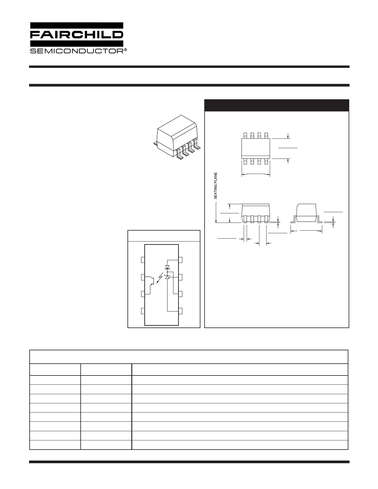
FUNCTIONAL BLOCK DIAGRAM
NC 1
C2
E3
8 LED
7 FB
6 COMP
APPLICATIONS
NC 4
5 GND
• Power system for workstations
• Telecom central office supply
• Telecom bricks
PACKAGE DIMENSIONS
0.164 (4.16)
0.144 (3.66)
1
0.202 (5.13)
0.182 (4.63)
0.143 (3.63)
0.123 (3.13)
0.010 (0.25)
0.006 (0.16)
0.021 (0.53)
0.011 (0.28)
0.008 (0.20)
0.003 (0.08)
0.050 (1.27)
TYP
0.244 (6.19)
0.224 (5.69)
Lead Coplanarity : 0.004 (0.10) MAX
NOTE
All dimensions are in inches (millimeters)
PIN DEFINITIONS
Pin Number
Pin Name
Pin function description
1 NC Not connected
2 C Phototransistor Collector
3 E Phototransistor Emitter
4 NC Not connected
5
GND
Ground
6
COMP
Error Amplifier Compensation. This pin is the output of the error amplifier. *
7 FB Voltage Feedback. This pin is the inverting input to the error amplifier
8 LED Anode LED. This pin is the input to the light emitting diode.
* The compensation network must be attached between pins 6 and 7.
© 2003 Fairchild Semiconductor Corporation
Page 1 of 13
4/10/03
1 page 
OPTICALLY ISOLATED
ERROR AMPLIFIER
I(LED)
8
VF
6
V7
VREF
5
2
3
V
FOD2712
I(LED)
8
2
R1 6
7
R2 VREF
5
VCOMP
3
FIG. 1. VREF, VF, ILED (min) TEST CIRCUIT
FIG. 2. ∆VREF/∆VCOMP TEST CIRCUIT
I(LED)
8
IREF
6
V7
R1
5
2
3
FIG. 3. IREF TEST CIRCUIT
ICEO
82
VCE
6
3
7
5
I(OFF)
V(LED)
V
8
6
7
5
2
3
FIG. 4. I(OFF) TEST CIRCUIT
I(LED)
V
8
6
7
VREF
5
I(C)
2
VCE
3
VCOMP
FIG. 5. ICEO TEST CIRCUIT
© 2003 Fairchild Semiconductor Corporation
Page 5 of 13
FIG. 6. CTR, VCE(sat) TEST CIRCUIT
4/10/03
5 Page 
OPTICALLY ISOLATED
ERROR AMPLIFIER
ORDERING INFORMATION
Example: FOD2712
X
Y
X
Packaging Option
R1: Tape and Reel (500 per reel)
R2: Tape and Reel (2,500 per reel)
Y
V:VDE tested
MARKING INFORMATION
1
2712 2
V X YY S 6
FOD2712
3 45
Definitions
1 Fairchild logo
2 Device number
3
VDE mark (Note: Only appears on parts ordered with VDE
option – See order entry table)
4 One digit year code, e.g., ‘3’
5 Two digit work week ranging from ‘01’ to ‘53’
6 Assembly package code
© 2003 Fairchild Semiconductor Corporation
Page 11 of 13
4/10/03
11 Page | ||
| Páginas | Total 13 Páginas | |
| PDF Descargar | [ Datasheet FOD2712.PDF ] | |
Hoja de datos destacado
| Número de pieza | Descripción | Fabricantes |
| FOD2711 | optically isolated error amplifier | Fairchild Semiconductor |
| FOD2712 | OPTICALLY ISOLATED ERROR AMPLIFIER | Fairchild Semiconductor |
| FOD2712 | Power Conversion for the Data Communications Market | Fairchild Semiconductor |
| Número de pieza | Descripción | Fabricantes |
| SLA6805M | High Voltage 3 phase Motor Driver IC. |
Sanken |
| SDC1742 | 12- and 14-Bit Hybrid Synchro / Resolver-to-Digital Converters. |
Analog Devices |
|
DataSheet.es es una pagina web que funciona como un repositorio de manuales o hoja de datos de muchos de los productos más populares, |
| DataSheet.es | 2020 | Privacy Policy | Contacto | Buscar |