|
|
|
PDF X9241 Data sheet ( Hoja de datos )
| Número de pieza | X9241 | |
| Descripción | Quad E2POT Nonvolatile Digital Potentiometer | |
| Fabricantes | Xicor | |
| Logotipo | ||
Hay una vista previa y un enlace de descarga de X9241 (archivo pdf) en la parte inferior de esta página. Total 16 Páginas | ||
|
No Preview Available !
APPLICATION NOTES AND DEVELOPMENT SYSTEM
AVA I L A B L E
AN20 • AN42–48 • AN50–53 • AN73 • XK9241
TXe9r2m41inal Voltage ±5V, 64 Taps
X9241
Quad E2POT™ Nonvolatile Digital Potentiometer
FEATURES
• Four E2POTs in One Package
• Two-Wire Serial Interface
• Register Oriented Format
—Directly Write Wiper Position
—Read Wiper Position
—Store as Many as Four Positions per Pot
• Instruction Format
—Quick Transfer of Register Contents to
Resistor Array
—Cascade Resistor Arrays
• Low Power CMOS
• Direct Write Cell
—Endurance - 100,000 Data Changes per Register
—Register Data Retention - 100 years
• 16 Bytes of E2PROM memory
• 3 Resistor Array Values
—2KΩ to 50KΩ Mask Programmable
—Cascadable For Values of 500Ω to 200KΩ
• Resolution: 64 Taps each Pot
• 20-Lead Plastic DIP, 20-Lead TSSOP and
20-Lead SOIC Packages
DESCRIPTION
The X9241 integrates four nonvolatile E2POT digitally
controlled potentiometers on a monolithic CMOS micro-
circuit.
The X9241 contains four resistor arrays, each com-
posed of 63 resistive elements. Between each element
and at either end are tap points accessible to the wiper
elements. The position of the wiper element on the array
is controlled by the user through the two-wire serial bus
interface.
Each resistor array has associated with it a wiper counter
register and four 8-bit data registers that can be directly
written and read by the user. The contents of the wiper
counter register control the position of the wiper on the
resistor array.
The data register may be read or written by the user. The
contents of the data registers can be transferred to the
wiper counter register to position the wiper. The current
wiper position can be transferred to any one of its
associated data registers.
The arrays may be cascaded to form resistive elements
with 127, 190 or 253 taps.
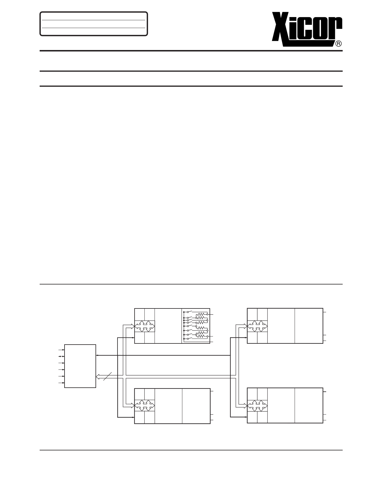
FUNCTIONAL DIAGRAM
SCL
SDA
A0
A1
A2
A3
INTERFACE
AND
CONTROL
CIRCUITRY
8
DATA
R0 R1
WIPER
COUNTER
REGISTER
R2 R3 (WCR)
VH0
VL0
VW0
R0 R1 WIPER
COUNTER RESISTOR
REGISTER ARRAY
R2 R3 (WCR)
POT 1
VH1
VL1
VW1
R0 R1 WIPER RESISTOR
COUNTER ARRAY
REGISTER POT 2
R2 R3 (WCR)
VH2
VL2
VW2
R0 R1 WIPER RESISTOR
COUNTER ARRAY
REGISTER POT 3
R2 R3 (WCR)
VH3
VL3
VW3
3864 ILL F07.1
© Xicor, Inc. 1994, 1995, 1996 Patents Pending
3864-2.7 7/1/96 T0/C3/D3 NS
1
Characteristics subject to change without notice
1 page 
X9241
Figure 4. Three-Byte Command Sequence
SCL
SDA
S 0 1 0 1 A3 A2 A1 A0 A I3 I2 I1 I0 P1 P0 R1 R0 A CM DW D5 D4 D3 D2 D1 D0 A S
TC C
CT
AK K
KO
RP
T
3864 ILL F11
Figure 5. Increment/Decrement Command Sequence
SCL
SDA
XX
S 0 1 0 1 A3 A2 A1 A0 A I3 I2 I1 I0 P1 P0 R1 R0 A I I
T C CN N
A K KCC
R 12
T
ID
NE
CC
n1
DS
ET
CO
nP
3864 FHD F12
Figure 6. Increment/Decrement Timing Limits
INC/DEC
CMD
ISSUED
SCL
SDA
tCLWV
VW VOLTAGE OUT
5
3864 ILL F13
5 Page 
X9241
A.C. CHARACTERISTICS (Over recommended operating conditions unless otherwise stated)
Limits
Symbol
Parameter
Min.
Max.
Units
fSCL SCL Clock Frequency
0 100 KHz
tLOW
tHIGH
tR
tF
Ti
Clock LOW Period
Clock HIGH Period
SCL and SDA Rise Time
SCL and SDA Fall Time
Noise Suppression Time Constant
(Glitch Filter)
4700
4000
1000
300
100
ns
ns
ns
ns
ns
tSU:STA
Start Condition Setup Time (for a Repeated
Start Condition)
4700
ns
tHD:STA
tSU:DAT
tHD:DAT
tAA
tDH
tSU:STO
tBUF
tWR
tSTPWV
tCLWV
tR VCC
Start Condition Hold Time
Data in Setup Time
Data in Hold Time
SCL LOW to SDA Data Out Valid
Data Out Hold Time
Stop Condition Setup Time
Bus Free Time Prior to New Transmission
Write Cycle Time (Nonvolatile Write Operation)
Wiper Response Time From Stop Generation
Wiper Response From SCL LOW
VCC Power-up Rate
4000
250
0
300
300
4700
4700
0.2
3500
10
500
1000
50
ns
ns
ns
ns
ns
ns
ns
ms
µs
µs
mV/µs
Reference
Figure
10
10
10
10
10
10
10 & 12
10 & 12
10
10
11
11
10 & 12
10
13
13
6
3864 PGM T11.3
Figure 10. Input Bus Timing
tHIGH
SCL
SDA
(DATA IN)
tSU:STA
tHD:STA tHD:DAT
tLOW
tF
tSU:DAT
tR
tSU:STO
tBUF
3864 ILL F03
11
11 Page | ||
| Páginas | Total 16 Páginas | |
| PDF Descargar | [ Datasheet X9241.PDF ] | |
Hoja de datos destacado
| Número de pieza | Descripción | Fabricantes |
| X9241 | Quad E2POT Nonvolatile Digital Potentiometer | Xicor |
| X9241A | Quad Digitally Controlled Potentiometer (XDCP) | Xicor |
| X9241A | Quad Digital Controlled Potentionmeters | Intersil Corporation |
| Número de pieza | Descripción | Fabricantes |
| SLA6805M | High Voltage 3 phase Motor Driver IC. |
Sanken |
| SDC1742 | 12- and 14-Bit Hybrid Synchro / Resolver-to-Digital Converters. |
Analog Devices |
|
DataSheet.es es una pagina web que funciona como un repositorio de manuales o hoja de datos de muchos de los productos más populares, |
| DataSheet.es | 2020 | Privacy Policy | Contacto | Buscar |