|
|
|
PDF VN02AN012Y Data sheet ( Hoja de datos )
| Número de pieza | VN02AN012Y | |
| Descripción | HIGH SIDE SMART POWER SOLID STATE RELAY | |
| Fabricantes | STMicroelectronics | |
| Logotipo | ||
Hay una vista previa y un enlace de descarga de VN02AN012Y (archivo pdf) en la parte inferior de esta página. Total 11 Páginas | ||
|
No Preview Available !
www.DataSheet4U.com
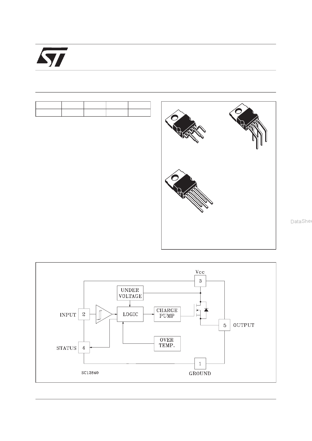
® VN02AN
HIGH SIDE SMART POWER SOLID STATE RELAY
TYPE
V N02 AN
VDSS
60 V
RD S(on )
0.35 Ω
IOUT
7A
VCC
36 V
s OUTPUT CURRENT (CONTINUOUS):
7A @ Tc=25oC
s LOGIC LEVEL 5V COMPATIBLE INPUT
s THERMAL SHUT-DOWN
s UNDER VOLTAGE PROTECTION
s OPEN DRAIN DIAGNOSTIC OUTPUT
s FAST DEMAGNETIZATION OF INDUCTIVE
LOAD
PENTAWATT
(vertical)
PENTAWATT
(horizontal)
DESCRIPTION
The VN02AN is a monolithic device made using
STMicroelectronics VIPower Technology,
PENTAWATT
(in-line)
intended for driving resistive or inductive loads
with one side grounded.
Built-in thermal shut-down protects the chip from
over temperature and short circuit.
DataSheet4U.com
ORDER CODES:
The diagnostic output indicates an over
PENTAWATT vertical
VN02AN
temperature status.
PENTAWATT horizontal VN02AN(011Y)
Fast turn-off of inductive load is achieved by
PENTAWATT in-line
VN02AN(012Y)
negative (-18 V) load voltage at turn-off.
BLOCK DIAGRAM
DataShee
July 1998
DataSheet4U.com
1/11
1 page 
www.DataSheet4U.com
VN02AN
et4U.com
FUNCTIONAL DESCRIPTION
where f = Switching Frequency
The device has a diagnostic output which
indicates over temperature conditions.
Based on this formula it is possible to know the
value of inductance and/or current to avoid a
The truth table shows input, diagnostic output thermal shut-down.
status and output voltage level in normal
operation and fault conditions. The output signals PROTECTING THE DEVICE AGAINST RE-
are processed by internal logic.
VERSE BATTERY
To protect the device against short circuit and
over current conditions, the thermal protection
turns the integrated Power MOS off at a minimum
junction temperature of 140 oC. When the
temperature returns to 125 oC the switch is
automatically turned on again. To ensure the
The simpliest way to protect the device against a
continuous reverse battery voltage (-36V) is to
insert a Schottky diode between pin 1 (GND) and
ground, as shown in the typical application circuit
(Fig. 3). The consequences of the voltage drop
across this diode are as follows:
protection in all VCC conditions and in all the
junction temperature range it is necessary to limit
If the input is pulled to power GND, a negative
voltage of -Vf is seen by the device. (Vil, Vih
the voltage drop across Drain and Source (pin 3 thresholds and Vstat are increased by Vf with
and 5) at 28V according to:
respect to power GND).
Vds = VCC - IOV * (Ri + Rw + Rl)
where:
The undervoltage shut-down level is increased by
Vf.
Ri = internal resistence of Power Supply
If there is no need for the control unit to handle
Rw = Wires resistance
external analog signals referred to the power
Rl = Short Circuit resistance
GND, the best approach is to connect the
Driving inductive loads, an internal function of the reference potential of the control unit to node [1]
device ensures the fast demagnetization with (see application circuit in fig. 4), which becomes
typical voltage (Vdemag) of -18V.
This function allows the reduction of
dissipation according to the formula:
the DpaotwaeSrheet4stbUhooe.lacurotcdimoonmaavmlolooidwninssgtihgsenhauilfsteGoNoffDVaihfso,tar Vntidhl aeardnwddhiooVldeseta.ct.onTthroisl
Pdem = 0.5 * Lload * (Iload)2 * [(VCC + Vdem)/Vdem] * f
Figure 2: Over Current Test Circuit
DataShee
DataSheet4U.com
5/11
5 Page 
www.DataSheet4U.com
VN02AN
et4U.com
DataSheet4U.com
Information furnished is believed to be accurate and reliable. However, STMicroelectronics assumes no responsibility for the consequences
of use of such information nor for any infringement of patents or other rights of third parties which may result from its use. No license is
granted by implication or otherwise under any patent or patent rights of STMicroelectronics. Specification mentioned in this publication are
subject to change without notice. This publication supersedes and replaces all information previously supplied. STMicroelectronics products
are not authorized for use as critical compone nts in life support devices or systems without express written approval of STMicroelectronics.
The ST logo is a trademark of STMicroelectronics
© 1998 STMicroelectronics – Printed in Italy – All Rights Reserved
STMicroelectronics GROUP OF COMPANIES
Australia - Brazil - Canada - China - France - Germany - Italy - Japan - Korea - Malaysia - Malta - Mexico - Morocco - The Netherlands -
Singapore - Spain - Sweden - Switzerland - Taiwan - Thailand - United Kingdom - U.S.A.
.
DataSheet4U.com
11/11
11 Page | ||
| Páginas | Total 11 Páginas | |
| PDF Descargar | [ Datasheet VN02AN012Y.PDF ] | |
Hoja de datos destacado
| Número de pieza | Descripción | Fabricantes |
| VN02AN012Y | HIGH SIDE SMART POWER SOLID STATE RELAY | STMicroelectronics |
| Número de pieza | Descripción | Fabricantes |
| SLA6805M | High Voltage 3 phase Motor Driver IC. |
Sanken |
| SDC1742 | 12- and 14-Bit Hybrid Synchro / Resolver-to-Digital Converters. |
Analog Devices |
|
DataSheet.es es una pagina web que funciona como un repositorio de manuales o hoja de datos de muchos de los productos más populares, |
| DataSheet.es | 2020 | Privacy Policy | Contacto | Buscar |