|
|
|
PDF M74HCT7259 Data sheet ( Hoja de datos )
| Número de pieza | M74HCT7259 | |
| Descripción | 8BIT ADDRESSABLE LATCH/DECODER/RELAIS DRIVER OPEN DRAIN /INVERTING OUTPUT | |
| Fabricantes | ST Microelectronics | |
| Logotipo | ||
Hay una vista previa y un enlace de descarga de M74HCT7259 (archivo pdf) en la parte inferior de esta página. Total 11 Páginas | ||
|
No Preview Available !
® M74HCT7259
8BIT ADDRESSABLE LATCH/DECODER/RELAIS
DRIVER (OPEN DRAIN,INVERTING OUTPUT)
s LOW POWER DISSIPATION
ICC = 4 µA (MAX.) AT TA = 25 °C
s COMPATIBLE WITH TTL OUTPUTS
VIH = 2V (MIN) VIL = 0.8V (MAX) AT 5V
s OUTPUT DRIVE CAPABILITY
90 LSTTL LOADS
s HIGH CURRENT OPEN DRAIN OUTPUT UP
TO 80 mA
The M74HCT7259 is a high speed CMOS 8 BIT
ADDRESSABLE LATCH/DECODER fabricated in
silicon gate C2MOS technology. It has the same
high speed performance of LSTTL combined with
true CMOS low power consumption.
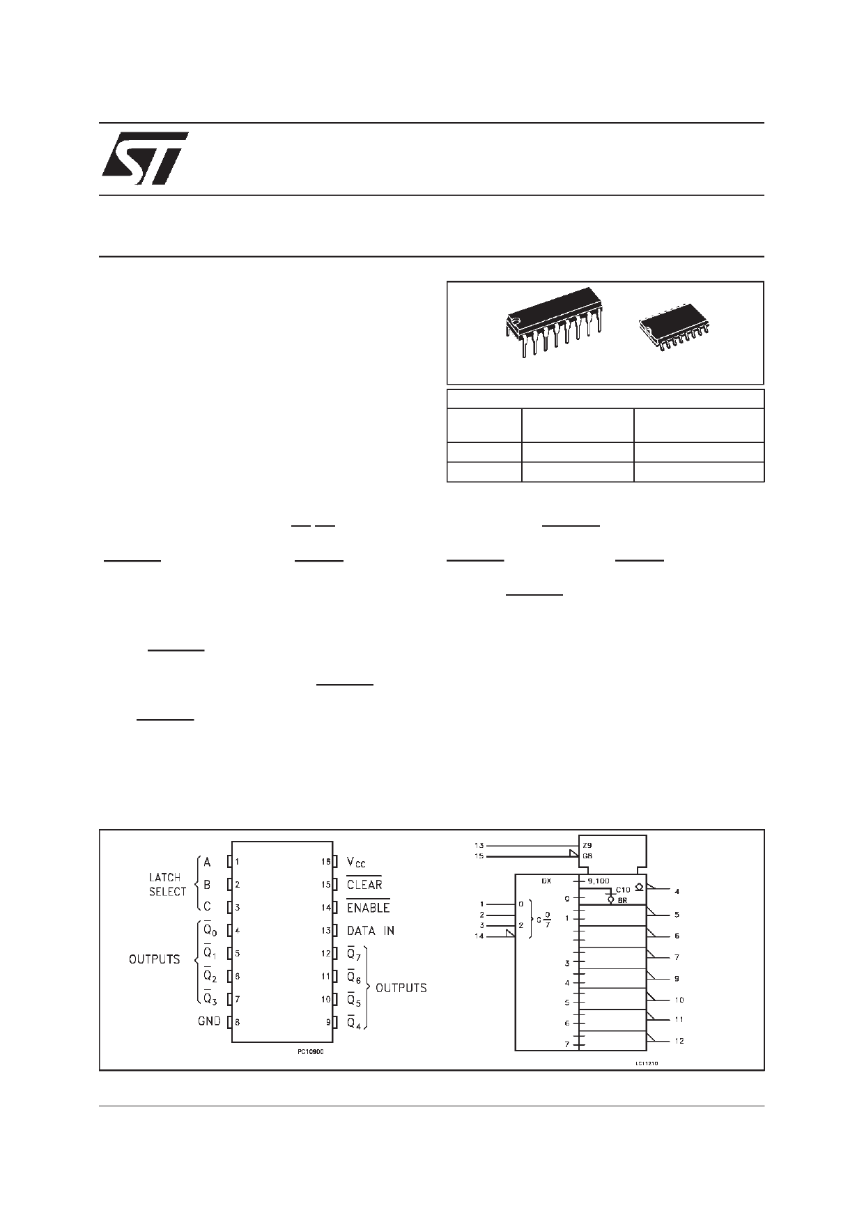
The M74HCT7259 has single data input (D) 8
LATCH inverted OUTPUTS (Q0-Q7), 3 address
inputs (A, B and C), common enable input
(ENABLE) and a common CLEAR input. To
operate this device as an addressable latch, data
is held on the D input, and the address of the
latch into which the data is to be entered is held
on the A, B and C inputs.
When ENABLE is taken low the data flows
through to the address output. The data is stored
on the positive-going edge of the ENABLE pulse.
All unadressed latches will remain unaffected.
With ENABLE in the high state the device is
deselected and all latches remain in their
previous state, unaffected by changes on the
PRELIMINARY DATA
PACKAGE
DIP SOP
ORDER CODES
T UBE
T&R
DIP
SOP
M74HCT7259B1R
M74HCT7259M1R M74HCT7259M1RTR
data or address inputs. To eliminate the
possibility of entering erroneous data into the
latches, the ENABLE should be held high
(inactive) while the address lines are changing. If
ENABLE is held high and CLEAR is taken low all
eight latches are cleared to the HIGH (OFF)
state. If ENABLE is low all latches except the
addressed latch will be cleared. The address
latch will instead be the complement of the D
input,effectively implementing a 3 to 8 line
decoder. Internal clamp diodes protect the open
drain outputs against over voltages due to
inductive loads.
All inputs are equipped with protection circuits
against static discharge and transient excess
voltage.
PIN CONNECTION AND IEC LOGIC SYMBOLS
February 2000
1/11
1 page 
M74HCT7259
AC ELECTRICAL CHARACTERISTICS (CL = 50 pF, Input tr = tf = 6 ns)
Symb ol
Parameter
tTLH Output Transition Time
tPLZ Propagation Delay Time
tPZL (DATA - Q)
Test Conditions
VCC CL
(V) (pF)
RL
(KΩ)
3.3(*) 50
1
4.5
3.3(*)
3.3(*)
50
50
150
1
1
1
4.5 50
1
Valu e
TA = 25 oC
-40 to 85 oC
Min. T yp. Max. Min. Max.
18
36
9
80
92
20 31
39
Un it
ns
ns
tPLZ Propagation Delay Time
tPZL (A, B, C - Q)
4.5
3.3(*)
3.3(*)
150
50
150
4.5 50
1
1
1
1
24 37
25 39
46
98
112 ns
49
tPLZ Propagation Delay Time
tPZL (ENABLE - Q)
4.5
3.3(*)
3.3(*)
150
50
150
4.5 50
1
1
1
1
29 45
21 33
56
82
98 ns
41
tPLZ Propagation Delay Time
tPZL (CLEAR - Q)
4.5
3.3(*)
3.3(*)
150
50
150
4.5 50
1
1
1
1
25 39
19 30
49
76
90 ns
38
4.5 150
tW(L) Minimum Pulse Width (CLEAR) 3.3(*) 50
4.5 50
tW(L) Minimum Pulse Width (ENABLE) 3.3(*) 50
4.5 50
ts Minimum Set-Up Time
3.3(*) 50
4.5 50
th Minimum Hold Time
3.3(*) 50
4.5 50
1
1
1
1
1
1
1
1
1
23 36
7 15
7 15
4 10
5
45
38 ns
19
38 ns
19
26 ns
13
10 ns
5
CIN Input Capacitance
5 10
10 pF
CPD (**) Power Dissipation Capacitance
96 pF
(*) Voltage Range is 3.3V ±5%
(**) CPD is defined as the value of theIC’s internal equivalent capacitance which is calculated from the operating current consumption without load. (Refer
toTest Circuit). Average operting current can be obtained by the following equation. ICC(opr) = CPD • VCC • fIN + ICC
5/11
5 Page 
M74HCT7259
Information furnished is believed to be accurate and reliable. However, STMicroelectronics assumes no responsibility for the consequences
of use of such information nor for any infringement of patents or other rights of third parties which may result from its use. No license is
granted by implication or otherwise under any patent or patent rights of STMicroelectronics. Specification mentioned in this publication are
subject to change without notice. This publication supersedes and replaces all information previously supplied. STMicroelectronics products
are not authorized for use as critical components in life support devices or systems withoutexpress written approval of STMicroelectronics.
The ST logo is a registered trademark of STMicroelectronics
© 2000 STMicroelectronics – Printed in Italy – All Rights Reserved
STMicroelectronics GROUP OF COMPANIES
Australia - Brazil - China - Finland - France - Germany - Hong Kong - India - Italy - Japan - Malaysia - Malta - Morocco
Singapore - Spain - Sweden - Switzerland - United Kingdom - U.S.A.
http://www.st.com
.
11/11
11 Page | ||
| Páginas | Total 11 Páginas | |
| PDF Descargar | [ Datasheet M74HCT7259.PDF ] | |
Hoja de datos destacado
| Número de pieza | Descripción | Fabricantes |
| M74HCT7259 | 8BIT ADDRESSABLE LATCH/DECODER/RELAIS DRIVER OPEN DRAIN /INVERTING OUTPUT | ST Microelectronics |
| Número de pieza | Descripción | Fabricantes |
| SLA6805M | High Voltage 3 phase Motor Driver IC. |
Sanken |
| SDC1742 | 12- and 14-Bit Hybrid Synchro / Resolver-to-Digital Converters. |
Analog Devices |
|
DataSheet.es es una pagina web que funciona como un repositorio de manuales o hoja de datos de muchos de los productos más populares, |
| DataSheet.es | 2020 | Privacy Policy | Contacto | Buscar |