|
|
|
PDF NW6005 Data sheet ( Hoja de datos )
| Número de pieza | NW6005 | |
| Descripción | ENHANCED TYPE II CALLER ID DECODER | |
| Fabricantes | Integrated Device Technology | |
| Logotipo | ||
Hay una vista previa y un enlace de descarga de NW6005 (archivo pdf) en la parte inferior de esta página. Total 20 Páginas | ||
|
No Preview Available !
ENHANCED TYPE II CALLER ID DECODER
NW6005
FEATURES
• 1200 baud Bell 202 and ITU-T V.23 Frequency Shift Keying
(FSK) Demodulation
• Compliant with following specifications:
Bellcore GR-30-CORE & SR-TSV-002476
TIA/EIA-716, TIA/EIA-777 Draft
British Telecom (BT) SIN227 & SIN242
ETSI ETS 300 778-1 and -2
• Bellcore “CPE Alerting Signal (CAS)”, British Telecom “Idle State
and Loop State Tone Alert Signal” and ETSI “Dual Tone Alerting
Signal (DT-AS)” detection
• Two seperate OP amps with adjustable gain for Tip/Ring and
Telephone Hybrid connections
• Monitoring of the stop bit for framing error check
• Serial FSK data interface with selectable output of bit stream or 1
byte buffer
• FSK carrier detection
• 3 V or 5 V operation
• Low power CMOS with intelligent powerdown mode
• Operating temperature range: -40 °C to +85 °C
• Packages available:
NW6005-XS 20 pin SOIC
(where ‘X’ is the revision ID)
DESCRIPTION
The NW6005 device is a single-chip, 3/5 Volt CMOS caller ID with
call waiting detection circuit. It can receive signals following Bellcore
GR-30-CORE & SR-TSV-002476, BT SIN227 & SIN242, and ETSI
ETS 300 788-1/-2 specifications.
The NW6005 provides 1200 baud Bell 202 and ITU-T V.23 FSK
demodulation and CAS/DT-AS detection. Two seperate differential
input amplifiers allow the device to be connected with both Tip/Ring
and Telephone Hybrid receive pair. FSK demodulation is
implemented only on Tip/Ring, while DT-AS (or CAS) detection can be
on either Tip/Ring or Hybrid Receive. In addition, NW6005 provides a
serial FSK data interface via which the data can be selected to be
processed as a bit stream or extracted from a 1 byte built-in buffer.
The device can be used in feature or cordless phones for BT
Calling Line Identity Presentation (CLIP), CCA CLIP and Bellcore
Calling Identity Delivery (CID) systems. It can also be used in caller ID
boxes, modem, fax machines, answering machines, database query
systems and Computer Telephony Integration (CTI) systems.
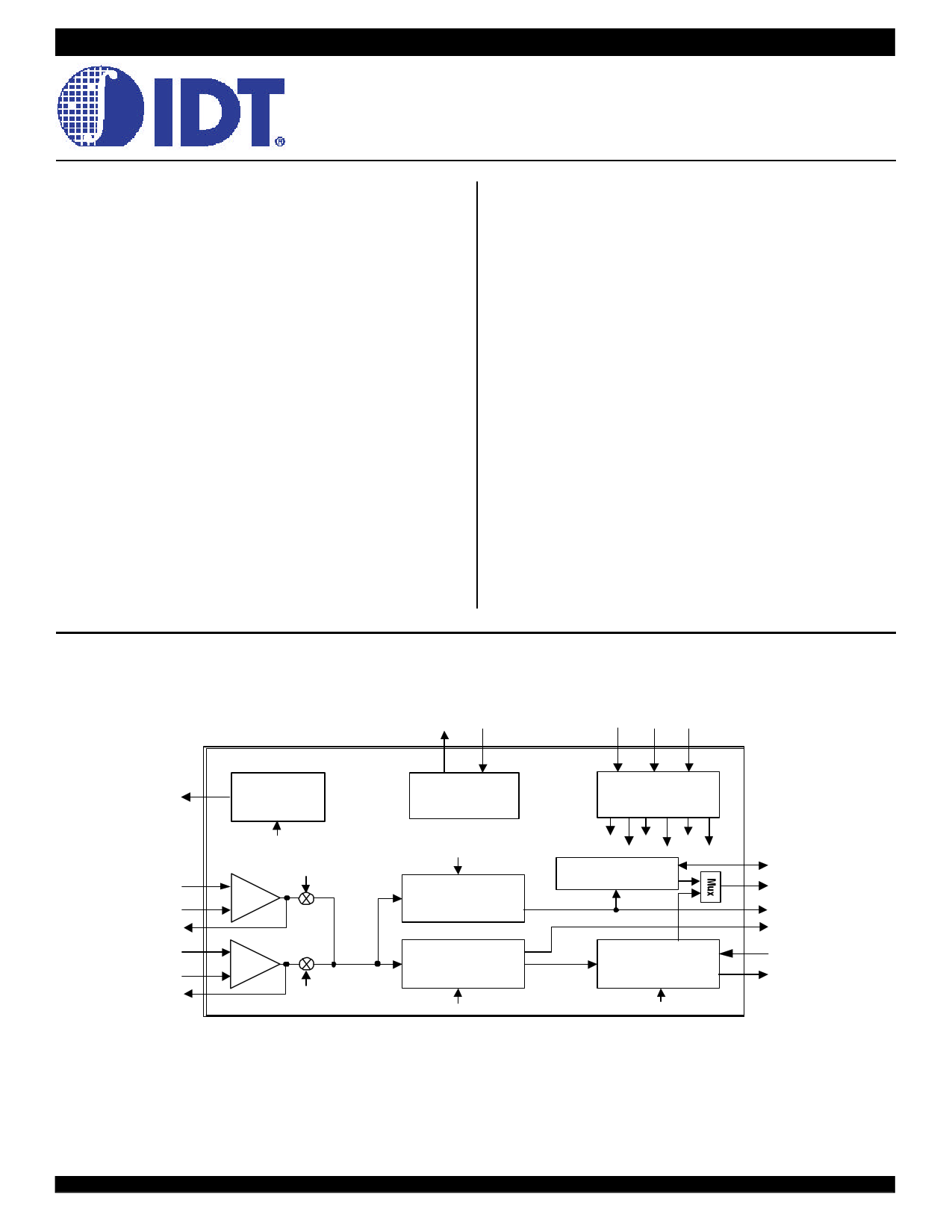
FUNCTIONAL BLOCK DIAGRAM
OSCOUT OSCIN
CB0 CB1 CB2
VREF
IN1+
IN1-
GS1
IN2+
IN2-
GS2
Bias
Generator
PWDN
GS1EN
+
-
+
-
GS2EN
Oscillator
CASEN
Dual Tone
Detector
FSK
Demodulator
FSKEN
Control Bit
Decoder
PWDN FSKEN GS1EN
CASEN MODE
GS2EN
Guard Time
Data/Timing Recovery
MODE
ST/GT
DR/STD
EST
CD
DCLK
DATA
Figure 1. Block Diagram
The IDT logo is a registered trademark of Integrated Device Technology, Inc
INDUSTRIAL TEMPERATURE RANGE
©2002 Integrated Device Technology, Inc.
JULY 2002
DSC-6048/3
1 page 
NW6005 ENHANCED TYPE II CALLER ID DECODER
INDUSTRIAL TEMPERATURE RANGE
DT-AS DETECTION ON EITHER TIP/RING OR HYBRID
RECEIVE PAIR
In off-hook services, the detection of Dual Tone Alert Signal (DT-AS)
will affect the quality of the call waiting service. Even though the end
office has muted the far end party before and after it sends DT-AS, the
near end user who is to receive the FSK information may be still
talking. Therefore, the CPE must be able to detect DT-AS successfully
in the presence of near end speech. Furthermore, imitation of DT-AS
by speech will also affect the DT-AS detector, thus false detection may
be generated.
To achieve better DT-AS detection quality, a method is to put DT-AS
detection on the telephone hybrid receive pair instead of on Tip/Ring.
As the near end speech has been attenuated while the DT-AS level is
the same as on Tip/Ring, the DT-AS immunity is improved.
A CPE capability called Multiple Extension Interworking(MEI), in
process of being defined by Bellcore, requests the CPE be capable of
detecting DT-AS when the line is off-hook, although the CPE itself may
be on-hook. Under some conditions, an on-hook CPE may send an
acknowledgment to the end office. Also, the on-hook CPE’s capability
of detecting DT-AS enables the call logs between on and off-hook
CPEs to be maintained synchronous. In this way, when all off-hook
CPEs are MEI compatible and DT-AS is received, one of the CPEs will
send the acknowledgment signal and all CPEs will receive FSK.
Therefore, if the DT-AS detector is connected only to the hybrid
receive pair, the CPE can not detect DT-AS when it is on-hook. When
the CPE is on-hook, either the hybrid is non-functional or the signal
level is severely attenuated. Thus, an on-hook CPE must be able to
detect DT-AS from Tip/Ring.
BLOCK DESCRIPTION
The NW6005 requires a 3.579545 MHz system clock and consists
of three major functional blocks: Analog Input Circuit, Dual Tone Alert
Signal Detection, and FSK Demodulation.
ANALOG INPUT CIRCUIT
The input signal is processed by the Analog Input Circuit block,
which is comprised of two OP amps and a bias source (VREF). VREF
is the output of a low impedance voltage source used to bias the input
OP amp, and is typically equal to VCC/2. The Tip/Ring OP amp
(IN1+, IN1-, GS1 pins) is for connecting to Tip and Ring, while the
Hybrid OP amp (IN2+, IN2-, GS2 pins) is for connecting to Hybrid
Receive Pair. The gain adjustable OP amps are also used to select
the input gain by connecting a feedback resistor between GS and the
IN- pin. Fig. 3 shows the differential input configuration. In single-
ended configuration, the gain adjustable OP amp is connected as
shown in Fig. 4.
R3 R4
VREF
NW6005
C1 R1
C2 R2
IN+
IN-
R5 GS
The NW6005 provides two input OP amps via which the device can
be connected both to Tip/Ring and to the Hybrid Receive pairs. Both
connection can be differential or single-ended. FSK demodulation is
implemented only on Tip/Ring, while DT-AS detection can be on either
Tip/Ring or Hybrid Receive. Tip/Ring DT-AS detection is required for
MEI and BT’s on-hook CLIP.
It should be noted here that as the Hybrid OP amp is for DT-AS
detection only, its gain can always be adjusted specifically for the DT-
AS signal.
Differential Input Amplifier
C1=C2
R1=R2 (For unity gain R5=R2)
R3=(R4R5)/(R4+R5)
Voltage Gain
Av = R5/R2
Input Impedance
Zin =2√R1²+ (1/ωC)²
Figure 3. Differential Input Gain Control Circuit
C Rin
NW6005
IN+
IN-
Rf GS
Voltage Gain
Av = Rf / Rin
VREF
Figure 4. Single-ended Input Gain Control Circuit
5
5 Page 
NW6005 ENHANCED TYPE II CALLER ID DECODER
INDUSTRIAL TEMPERATURE RANGE
A/B Wires
PWDN
Note6
FSKEN
Note6
CD
DR
Note7
DCLK
Note7
DATA
Al1esrttiRngingSiinggnal
A
Note 2
Note 5
Ch. Seizure
Mark
BC
D
...
..101010..
Message
E
2nd Ringing
F
Note 3
Note 2
Note 1
Note 4
...
Data
Figure 11. Bellcore On-hook Data Transmission Timing Diagram
Notes:
1) A= 2 sec typ., B= 250 - 500 ms, C= 250 ms, D= 150ms, E depends on data length, Max C+D+E = 2.9 - 3.7 sec, F ≥ 200 ms.
2) In a battery operated CPE, NW6005 may be enabled only after the end of ringing to conserve power.
3) The microcontroller in the CPE powers down the NW6005 after CD goes inactive.
4) The microcontroller times out if CD is not activated on the 2nd ring and puts the device into Power-down mode.
5) FSK may be always enabled while the CPE is on-hook. To prevent the FSK demodulator from reacting to other inband signals such as speech, DT-AS or DTMT tones. The designer may
choose to disable FSKduring the period that FSK signal is not expected.
6) PWDN and FSKEN are internal signals decoded from Control Bits CB2-0.
7) When CB0 is low, both DR and DCLK pins are unused.
11
11 Page | ||
| Páginas | Total 20 Páginas | |
| PDF Descargar | [ Datasheet NW6005.PDF ] | |
Hoja de datos destacado
| Número de pieza | Descripción | Fabricantes |
| NW6003 | TYPE II CALLER ID DECODER | Integrated Device Technology |
| NW6005 | ENHANCED TYPE II CALLER ID DECODER | Integrated Device Technology |
| NW6006 | ENHANCED TYPE II CALLER ID DECODER WITH STUTTER DIAL TONE DETECTOR | Integrated Device Technology |
| NW6006-XS | ENHANCED TYPE II CALLER ID DECODER WITH STUTTER DIAL TONE DETECTOR | Integrated Device Technology |
| Número de pieza | Descripción | Fabricantes |
| SLA6805M | High Voltage 3 phase Motor Driver IC. |
Sanken |
| SDC1742 | 12- and 14-Bit Hybrid Synchro / Resolver-to-Digital Converters. |
Analog Devices |
|
DataSheet.es es una pagina web que funciona como un repositorio de manuales o hoja de datos de muchos de los productos más populares, |
| DataSheet.es | 2020 | Privacy Policy | Contacto | Buscar |