|
|
|
PDF NWK933 Data sheet ( Hoja de datos )
| Número de pieza | NWK933 | |
| Descripción | 3.3V 10/100 Fast Ethernet Transceiver to MII | |
| Fabricantes | Mitel Networks | |
| Logotipo | ||
Hay una vista previa y un enlace de descarga de NWK933 (archivo pdf) en la parte inferior de esta página. Total 18 Páginas | ||
|
No Preview Available !
NWK933
NWK933
3.3V 10/100 Fast Ethernet Transceiver to MII
Features
q Integrated 10/100 Mbps Ethernet in a Single Chip
Solution
q Single 3.3V Power Supply
q Half Duplex and Full Duplex in both 10BASE-T
and 100BASE-TX
q Full MII for a Glueless MAC Connection
q Extended Register Set
q Integrated 10BASE-T Transceivers and Receive /
Transmit Filters
q Integrated Adaptive Equaliser and Base Line
Wander Correction (for FDDI Killer Packet)
q Full Auto-Negotiation Support for 10BASE-T and
100BASE-TX both Half and Full Duplex
q Link Status Change Interrupt
q Parallel Detection for Supporting Non Auto
Negotiation in Legacy Link Partners
q Low Dynamic Current
q Deep Sleep Low Power Mode <1mA
q Internal Power on Reset
q 64 pin 1mm thick TQFP Package
q Single Magnetics for 10BASE-T and 100BASE-TX
Operation for a Single RJ45 Connector
q Support for Flow Control 802.3 Specification
q Integrated 6 LED Driver
DS5029
Issue no 2.1
Odering Information
NWK933/CG/TP1N
May 1999
q Low External Component Count
q Loop-back mode for diagnostics
q Intelligent power management
(auto shutdown, auto wake)
q Low Transmit Jitter
Description
The NWK933 is a single chip 3.3V CMOS physical
layer solution from MII to the magnetics. It is designed
for 10BASE-T and 100BASE-TX Ethernet, based
on the IEEE 802.3 specifications.
The NWK933 is compatible with the Auto Negotiation
section of IEEE 802.3u and provides all the support
needed for the 802.3 Full duplex specification.
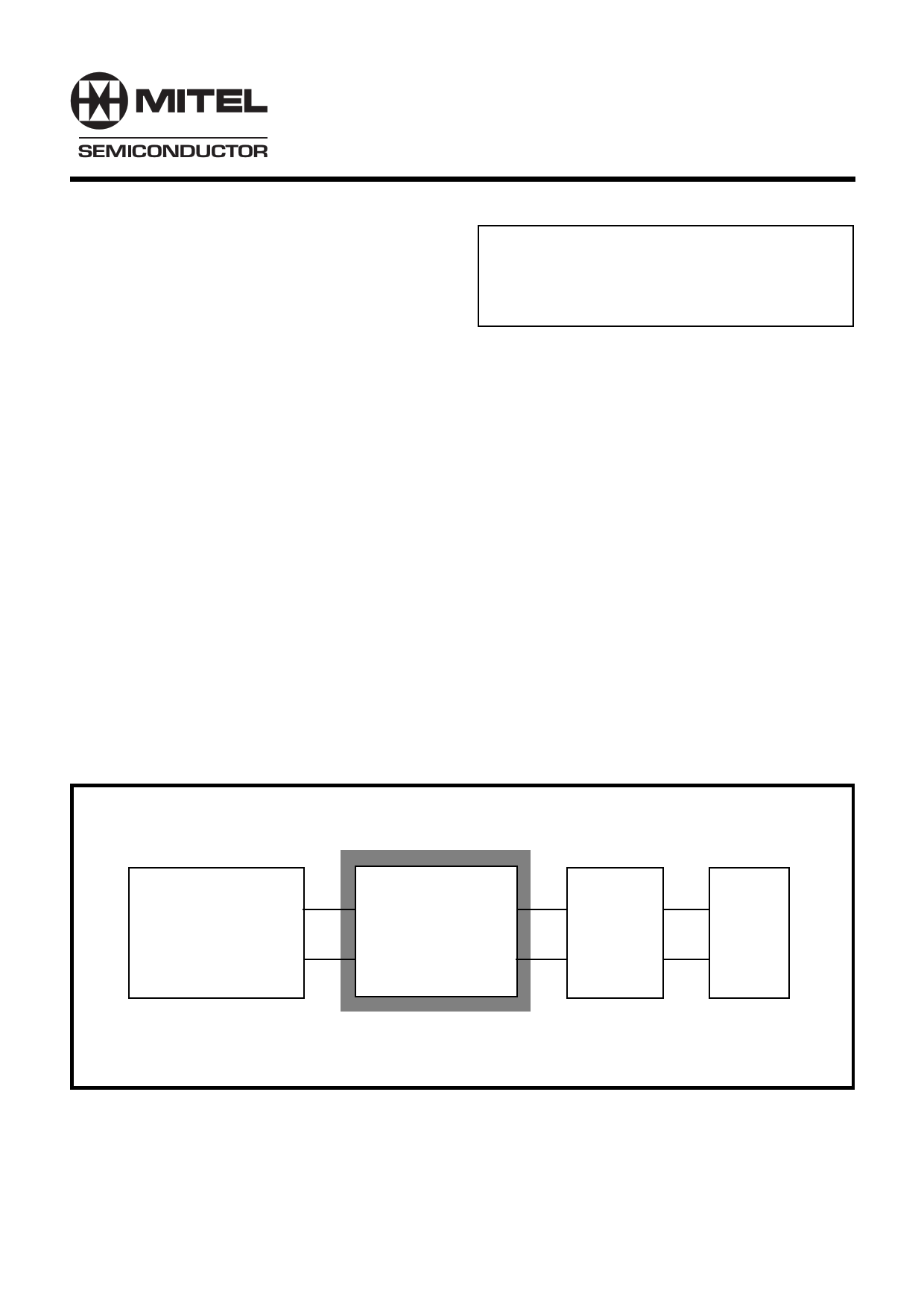
Switch or MAC
NWK933
Isolation
Magnetics
RJ45
Figure 1 System block diagram
1
1 page 
NWK933
TX_EN TX_ER
TXD [3:0]
Indication
0X
ignored
Normal inter frame data
1 0 0000 through 1111 Normal data transmission
1 1 0000 through 1111 Transmit error propagation
Figure 3. 100Mb/s Transmit Error States
100Mb/s Receive Errors
When there is no data on the cable, the receiver will
see only the idle code of scrambled 1’s. If a non idle
symbol is detected, the receiver looks for the SSD so
that it can align the incoming message for decoding.
If any 2 non consecutive zeros are detected within 10
bits, but are not the SSD symbols a false carrier
indication is signalled to the MII by asserting RX_ER
and setting RXD[3:0] to 1110 whilst keeping RX_DV
inactive. The remainder of the message is ignored
until 10 bits of 1’s are detected.
If any data is decoded after a SSD which is neither a
valid data code nor an ESD, then an error is flagged
by setting RX_ER active whilst the RX_DV signal is
active. This also happens if 2 idle codes are detected
before a valid ESD has been received or descramble
synchronisation is lost during packet reception. The
states of RX_DV and RX_ER are summarised in
Figure 4. RX_ER is clocked on the falling edge of
RX_CLK, and will remain active for at least 1 period
of RX_CLK.
RX_DV RX_ER
RXD [3:0]
Indication
0 0 0000 through 1111 Normal inter frame
01
1110
False carrier indication
1 0 0000 through 1111 Normal data reception
1 1 0101 or 0110 Data reception with errors
Figure 4. 100Mb/s receive error states
CONTROLS
Initialization, mode selection and other options are
governed by the control inputs and register as
described in the following paragraphs.
Initialization (RESET_N)
The NWK933 incorporates a power-on-reset circuit
for self-initialization on power-up. During initialization
the open-drain RESET_N pin is driven low and all
data outputs are disabled to prevent spurious outputs
to the twisted-pair and to the MII interface. RESET_N
will remain low until the power supply has been stable
for at least 400ns. The NWK933 will then release
RESET_N allowing the external pull-up to pull the pin
high. Device initialisation will not commence until
RESET_N is high. This allows the user to extend the
inactive period by externally holding RESET_N low.
It will not normally be necessary for the user to reset
the NWK933 because it is designed to automatically
recover from fault conditions. However, if required,
the user may initialize the device by doing a hardware
or software reset.
Reset Mode
There are two types of reset in the NWK933 - hardware
and software. The hardware reset is activated by
setting the RESET_N pin to logic 0, and holding it low
for at least 100ns. This mode causes an over-all reset
in the NWK933 - both analog and digital circuitry are
reset. Whilst RESET_N is low, the SPDST and FDST
pins are inputs, and are used to determine the speed
and duplex capability which will be advertised during
auto-neg. A low on SPDST advertises 100M capability.
A high on FDST advertises full duplex capability.
The software reset is activated by setting bit 15 in
register 0 high. This bit is a self clear bit and causes
a partial reset of the device.
Figure 5 summarises the different blocks to be reset
and which reset will affect them:
Block
management register
PCS state machine (RCV,
XMT, ANEG)
XMT scrambler
RCV scramble
control state machine
analog
HW Reset
yes
yes
SW reset
yes
yes
yes yes
yes yes
yes No
yes No
Figure 5. Effects of Reset
Note: Holding RESET_N low will hold the device in a static,
low power state.
5
5 Page 
reg 4- ANEG advertisement register
Bit
4.15
4.14
4.13
4.12:10
4.9:5
4.4:0
Bit name
NP
reserved
remote fault
reserved
Technology
selector
field
Description
Next page able - the NWK933 is not able to
perform next page
0 = no remote fault detected
1= a remote fault been detected
T4, 100Fdx, 100Hdx, 10Fdx, 10Hdx
reg 5- ANEG link partner ability register
Bit
5.15
5.14
5.13
5.12:5
5.4:0
Bit name
NP
ACK
remote fault
ability
selector field
Description
partner is next page capable
partner sent an acknowledge bit
partner detected a remote fault
partner’s technology ability
partner selector field
Default
0
0
0
0
0F
01
Default
0
0
0
0
0
reg 6- ANEG expansion register
Bit
6.15:5
6.4
6. 3
6.2
6.1
6.0
Bit name Description
Default
reserved
0
parallel
detect fault
0 = aneg process finished. No fault detected
1 = a fault has been detected
0
link partner 0 = Link partner is not next page able
next page able 1 = Link partner is next page able
0
next page
able
Page
received
0 = NWK933 is not able for next page
0 = no new page been received
1= a new page has been received and is in reg 5
0
0
link partner
aneg able
0 = Link partner is not aneg able
1 = Link partner is aneg able
0
reg 16, 17, 18, 19, 20 - Test registers
Bit Bit name Description
15:0 reserved test mode only
Default
0000
NWK933
R/W
RO
RO
R/W
R/W
R/W
R/W
R/W
RO
RO
RO
RO
RO
R/W
RO
RO
LH
RO
RO
RO
LH
RO
R/W
res
11
11 Page | ||
| Páginas | Total 18 Páginas | |
| PDF Descargar | [ Datasheet NWK933.PDF ] | |
Hoja de datos destacado
| Número de pieza | Descripción | Fabricantes |
| NWK933 | 3.3V 10/100 Fast Ethernet Transceiver to MII | Mitel Networks |
| NWK933CG | 3.3V 10/100 Fast Ethernet Transceiver to MII | Mitel Networks |
| NWK933TP1N | 3.3V 10/100 Fast Ethernet Transceiver to MII | Mitel Networks |
| Número de pieza | Descripción | Fabricantes |
| SLA6805M | High Voltage 3 phase Motor Driver IC. |
Sanken |
| SDC1742 | 12- and 14-Bit Hybrid Synchro / Resolver-to-Digital Converters. |
Analog Devices |
|
DataSheet.es es una pagina web que funciona como un repositorio de manuales o hoja de datos de muchos de los productos más populares, |
| DataSheet.es | 2020 | Privacy Policy | Contacto | Buscar |