|
|
|
PDF PM100RSE120 Data sheet ( Hoja de datos )
| Número de pieza | PM100RSE120 | |
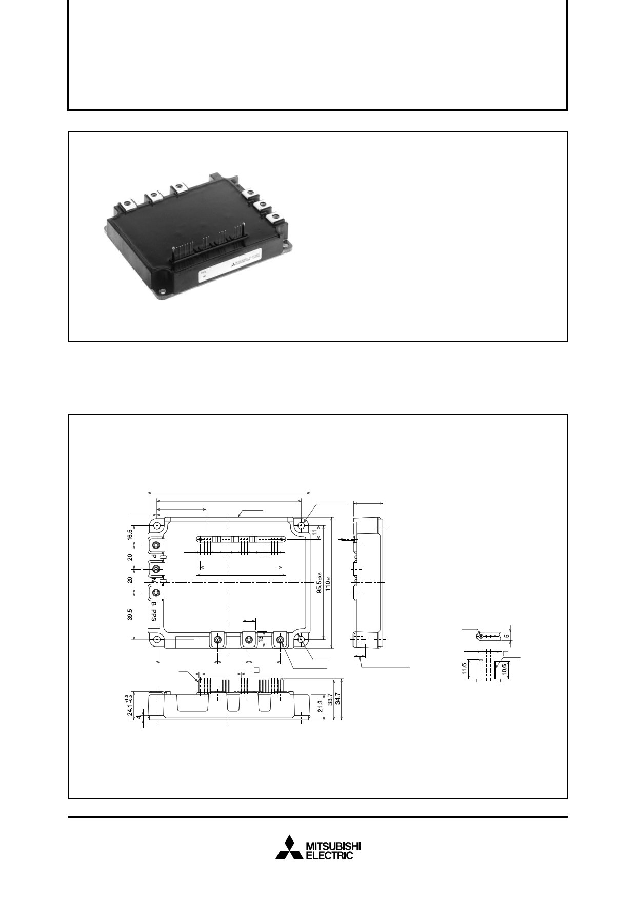
| Descripción | FLAT-BASE TYPE INSULATED PACKAGE | |
| Fabricantes | Mitsubishi Electric Semiconductor | |
| Logotipo | ||
Hay una vista previa y un enlace de descarga de PM100RSE120 (archivo pdf) en la parte inferior de esta página. Total 6 Páginas | ||
|
No Preview Available !
PM100RSE120
MITMSUITBSIUSBHIS<HINI T<EINLTLEIGLLEINGTENPOT WPOERWEMRODMUOLDEUSL>ES>
PM100PRMS10E0R1S2E0120
FLAFTL-BATA-SBEASTEYPTEYPE
INSIUNLSAUTLEADTEPDACPKAACGKEAGE
FEATURE
a) Adopting new 4th generation planar IGBT chip, which per-
formance is improved by 1µm fine rule process.
b) Using new Diode which is designed to get soft reverse
recovery characteristics.
• 3φ 100A, 1200V Current-sense IGBT for 15kHz switching
• 50A, 1200V Current-sense regenerative brake IGBT
• Monolithic gate drive & protection logic
• Detection, protection & status indication circuits for over-
current, short-circuit, over-temperature & under-voltage
• Acoustic noise-less 18.5/22kW class inverter application
APPLICATION
General purpose inverter, servo drives and other motor controls
PACKAGE OUTLINES
Dimensions in mm
0.5 ±0.3
39.7
135 ±1
120.5 ±0.5
LABEL
1 23
4 56
789
11 13 15
10 12 14 16
3.22 10.16 10.16 10.16
2-2.54 2-2.54 2-2.54 6-2.54
67.4
74.4
4- φ5.5
MOUNTING
HOLES
24.1
10.5
U VW
51.5
A
26 26
2-φ2.54
16- 0.64
4-R6
6-M5 NUTS
Screwing depth
Min9.0
Terminal code
1. VUPC
2. UP
3. VUP1
4. VVPC
5. VP
6. VVP1
7. VWPC
8. WP
9. VWP1
10. VNC
11. VN1
12. Br
13. UN
14. VN
15. WN
16. FO
φ2.54
3.22 2-2.54
0.64
A : DETAIL
Sep. 2001
1 page 
MITSUBISHI <INTELLIGENT POWER MODULES>
PM100RSE120
FLAT-BASE TYPE
INSULATED PACKAGE
PRECAUTIONS FOR TESTING
1. Before appling any control supply voltage (VD), the input terminals should be pulled up by resistores, etc. to their corre-
sponding supply voltage and each input signal should be kept off state.
After this, the specified ON and OFF level setting for each input signal should be done.
2. When performing “OC” and “SC” tests, the turn-off surge voltage spike at the corresponding protection operation should not
be allowed to rise above VCES rating of the device.
(These test should not be done by using a curve tracer or its equivalent.)
P, (U,V,W,B)
P, (U,V,W)
VCIN
(0V)
IN
(Fo)
V Ic
VCIN
(15V)
IN
(Fo)
V –Ic
VD (all) U,V,W, (N)
Fig. 1 VCE(sat) Test
VD (all) U,V,W,B, (N)
Fig. 2 VEC, (VFM) Test
a) Lower Arm Switching
P
VCIN
(15V)
VCIN
Signal input
(Upper Arm)
Signal input
(Lower Arm)
Fo
U,V,W
CS
Vcc
trr
Irr
90%
b) Upper Arm Switching VD (all)
VCIN
VCIN
(15V)
Signal input
(Upper Arm)
Signal input
(Lower Arm)
Fo
VD (all)
N
Ic
P
U,V,W
CS
N
Ic
10%
VCIN
Vcc td (on)
10%
tc (on)
tr
(ton= td (on) + tr)
Fig. 3 Switching time Test circuit and waveform
VCE
Ic
90%
10%
tc (off)
10%
td (off)
tf
(toff= td (off) + tf)
VCIN
(15V)
P, (U,V,W,B)
A
IN
(Fo) Pulse VCE
VCIN
Over Current
VD (all)
U,V,W, (N)
Fig. 4 ICES Test
P, (U,V,W,B)
VCIN
IN
(Fo)
VCC
VD (all)
U,V,W, (N)
IC
Fig. 5 OC and SC Test
IC
toff (OC)
Constant Current
OC
Short Circuit Current
Constant Current
SC
IC
Fig. 6 OC and SC Test waveform
P
VD
VCINP
U,V,W
Vcc
VD
VCINN
N
Ic
VCINP
0V
VCINN
0V
tdead
tdead
tdead
Fig. 7 Dead time measurement point example
t
t
Sep. 2001
5 Page | ||
| Páginas | Total 6 Páginas | |
| PDF Descargar | [ Datasheet PM100RSE120.PDF ] | |
Hoja de datos destacado
| Número de pieza | Descripción | Fabricantes |
| PM100RSE120 | FLAT-BASE TYPE INSULATED PACKAGE | Mitsubishi Electric Semiconductor |
| Número de pieza | Descripción | Fabricantes |
| SLA6805M | High Voltage 3 phase Motor Driver IC. |
Sanken |
| SDC1742 | 12- and 14-Bit Hybrid Synchro / Resolver-to-Digital Converters. |
Analog Devices |
|
DataSheet.es es una pagina web que funciona como un repositorio de manuales o hoja de datos de muchos de los productos más populares, |
| DataSheet.es | 2020 | Privacy Policy | Contacto | Buscar |