|
|
|
PDF ST6263 Data sheet ( Hoja de datos )
| Número de pieza | ST6263 | |
| Descripción | (ST6xxx) 8-BIT OTP/EPROM MCUs | |
| Fabricantes | ST Microelectronics | |
| Logotipo | ||
Hay una vista previa y un enlace de descarga de ST6263 (archivo pdf) en la parte inferior de esta página. Total 30 Páginas | ||
|
No Preview Available !
ST62T53C/T60C/T63C
ST62E60C
8-BIT OTP/EPROM MCUs WITH A/D CONVERTER,
SAFE RESET, AUTO-RELOAD TIMER, EEPROM AND SPI
s 3.0 to 6.0V Supply Operating Range
s 8 MHz Maximum Clock Frequency
s -40 to +125°C Operating Temperature Range
s Run, Wait and Stop Modes
s 5 Interrupt Vectors
s Look-up Table capability in Program Memory
s Data Storage in Program Memory:
User selectable size
s Data RAM: 128 bytes
s DataEEPROM: 64/128 bytes(noneonST62T53C)
s User Programmable Options
s 13 I/O pins, fully programmable as:
– Input with pull-up resistor
– Input without pull-up resistor
– Input with interrupt generation
– Open-drain or push-pull output
– Analog Input
s 6 I/O lines can sink up to 30mA to drive LEDs or
TRIACs directly
s 8-bit Timer/Counter with 7-bit programmable
prescaler
s 8-bit Auto-reload Timer with 7-bit programmable
prescaler (AR Timer)
s Digital Watchdog
s Oscillator Safe Guard
s Low Voltage Detector for Safe Reset
s 8-bit A/D Converter with 7 analog inputs
s 8-bit Synchronous Peripheral Interface (SPI)
s On-chip Clock oscillator can be driven by Quartz
Crystal Ceramic resonator or RC network
s User configurable Power-on Reset
s One external Non-Maskable Interrupt
s ST626x-EMU2 Emulation and Development
System (connects to an MS-DOS PC via a
parallel port).
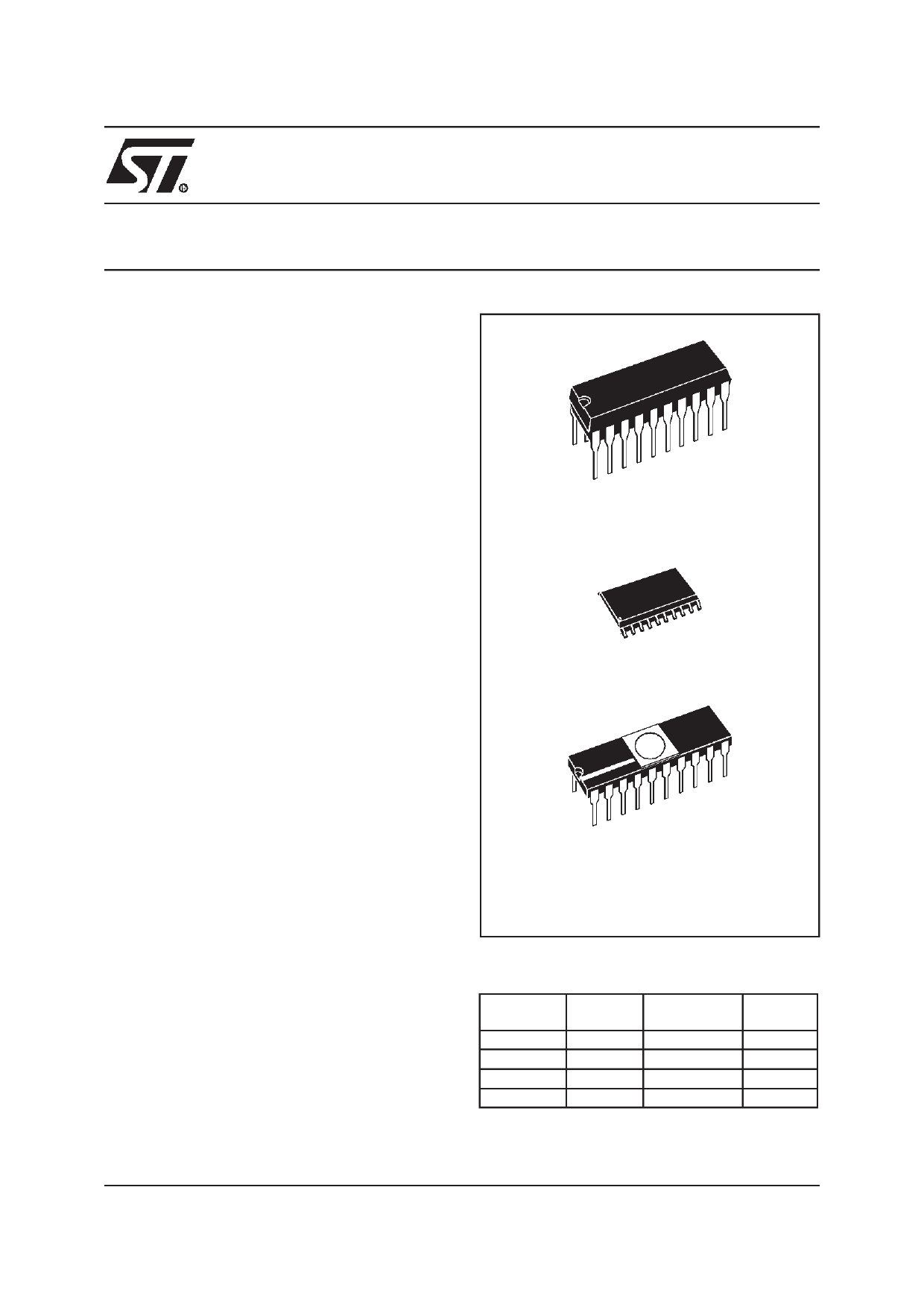
PDIP20
PSO20
CDIP20W
(See end of Datasheet for Ordering Information)
DEVICE SUMMARY
DEVICE OTP (Bytes)
ST62T53C
ST62T60C
ST62T63C
ST62E60C
1836
3884
1836
-
EPROM
(Bytes)
-
-
-
3884
EEPROM
-
128
64
128
November 1999
Rev. 2.6
1/86
1
1 page 
ST62T53C/T60C/T63C ST62E60C
1 GENERAL DESCRIPTION
1.1 INTRODUCTION
The ST62T53C, ST62T60C, ST62T63C and
ST62E60C devices are low cost members of the
ST62xx 8-bit HCMOS family of microcontrollers,
which is targeted at low to medium complexity ap-
plications. All ST62xx devices are based on a
building block approach: a common core is sur-
rounded by a number of on-chip peripherals.
The ST62E60C is the erasable EPROM version of
the ST62T60C device, which may be used to em-
ulate the ST62T53C, ST62T60C and ST62T63C
devices, as well as the respective ST6253C,
ST6260B and ST6263B ROM devices.
OTP and EPROM devices are functionally identi-
cal. The ROM based versions offer the same func-
tionality selecting as ROM options the options de-
Figure 1. Block Diagram
fined in the programmable option byte of the OTP/
EPROM versions.
OTP devices offer all the advantages of user pro-
grammability at low cost, which make them the
ideal choice in a wide range of applications where
frequent code changes, multiple code versions or
last minute programmability are required.
These compact low-cost devices feature a Timer
comprising an 8-bit counter and a 7-bit program-
mable prescaler, an 8-bit Auto-Reload Timer,
EEPROM data capability (except ST62T53C), a
serial port communication interface, an 8-bit A/D
Converter with 7 analog inputs and a Digital
Watchdog timer, making them well suited for a
wide range of automotive, appliance and industrial
applications.
TES T/VPP
NMI
TEST
8-BIT
A/D CONVERTER
IN TERRUPT
PROGRAM
MEMORY
1836 bytes OTP
(ST6 2T53C,T63C)
3884 bytes OTP
(ST62 T60C)
3884 bytes EPROM
(ST62E60C)
DATA ROM
USER
SE LECTABL E
DATA RAM
128 Bytes
DATA EEPROM
64 Bytes
(ST62T63C)
128 Bytes
(ST62T60C/E6 0C)
PC
STACK LEVEL 1
STACK LEVEL 2
STACK LEVEL 3
STACK LEVEL 4
STACK LEVEL 5
STACK LEVEL 6
8 BIT CORE
POWER
SUPPL Y
OSCILLAT OR
RESET
PORT A
PORT B
PORT C
AUTORELO AD
TIMER
TI MER
SPI (SERI AL
PERIPHE RAL
INTERFAC E)
DIGITAL
W ATCHDOG
PA0..PA3 / Ain
PB0..PB 3 / 30 mA Sink
PB6 / ARTimin / 30 mA Sink
PB7 / ARTimout / 30 mA Sink
PC2 / Sin / Ain
PC3 / Sout / Ain
PC4 / Sck / Ain
VDD VSS OSCin OSCout RESET
5/86
5
5 Page 
ST62T53C/T60C/T63C ST62E60C
MEMORY MAP (Cont’d)
1.3.6 Data RAM/EEPROM
(DRBR)
Address: E8h — Write only
Bank
Register
70
-
-
-
DRB R
4
-
-
DRBR DRBR
10
Bit 7-5 = These bits are not used
Bit 4 - DRBR4. This bit, when set, selects RAM
Page 2.
Bit 3-2 - Reserved. These bits are not used.
Bit 1 - DRBR1. This bit, when set, selects
EEPROM Page 1, when available.
Bit 0 - DRBR0. This bit, when set, selects
EEPROM Page 0, when available.
The selection of the bank is made by programming
the Data RAM Bank Switch register (DRBR regis-
ter) located at address E8h of the Data Space ac-
cording to Table 1. No more than one bank should
be set at a time.
The DRBR register can be addressed like a RAM
Data Space at the address E8h; nevertheless it is
a write only register that cannot be accessed with
single-bit operations. This register is used to select
the desired 64-byte RAM/EEPROM bank of the
Data Space. The bank number has to be loaded in
the DRBR register and the instruction has to point
to the selected location as if it was in bank 0 (from
00h address to 3Fh address).
This register is not cleared during the MCU initiali-
zation, therefore it must be written before the first
access to the Data Space bank region. Refer to
the Data Space description for additional informa-
tion. The DRBR register is not modified when an
interrupt or a subroutine occurs.
Notes :
Care is required when handling the DRBR register
as it is write only. For this reason, it is not allowed
to change the DRBR contents while executing in-
terrupt service routine, as the service routine can-
not save and then restore its previous content. If it
is impossible to avoid the writing of this register in
interrupt service routine, an image of this register
must be saved in a RAM location, and each time
the program writes to DRBR it must write also to
the image register. The image register must be
written first, so if an interrupt occurs between the
two instructions the DRBR is not affected.
In DRBR Register, only 1 bit must be set. Other-
wise two or more pages are enabled in parallel,
producing errors.
Care must also be taken not to change the
E PROM page (when available) when the parallel
writing mode is set for the E PROM, as defined in
EECTL register.
Table 3. Data RAM Bank Register Set-up
DRBR
ST62T53C
ST62T60C/E60C
ST62T63C
00 None
None
None
01
Not Available
EEPROM Page 0
EEPROM Page 0
02
Not Available
EEPROM Page 1
Not Available
08 Not Available
Not Available
Not Available
10h RAM Page 2
RAM Page 2
RAM Page 2
other
Reserved
Reserved
Reserved
11/86
11
11 Page | ||
| Páginas | Total 30 Páginas | |
| PDF Descargar | [ Datasheet ST6263.PDF ] | |
Hoja de datos destacado
| Número de pieza | Descripción | Fabricantes |
| ST6260 | (ST62xxx) 8-BIT OTP/EPROM MCUs | ST Microelectronics |
| ST6262 | (ST62xxx) 8-BIT OTP/EPROM MCUs | ST Microelectronics |
| ST6263 | (ST6xxx) 8-BIT OTP/EPROM MCUs | ST Microelectronics |
| ST6265B | 8-bit MCUs | STMicroelectronics |
| Número de pieza | Descripción | Fabricantes |
| SLA6805M | High Voltage 3 phase Motor Driver IC. |
Sanken |
| SDC1742 | 12- and 14-Bit Hybrid Synchro / Resolver-to-Digital Converters. |
Analog Devices |
|
DataSheet.es es una pagina web que funciona como un repositorio de manuales o hoja de datos de muchos de los productos más populares, |
| DataSheet.es | 2020 | Privacy Policy | Contacto | Buscar |