|
|
|
PDF NUD4301 Data sheet ( Hoja de datos )
| Número de pieza | NUD4301 | |
| Descripción | Dual Low Dropout Voltage LED Driver/Current Source | |
| Fabricantes | ON Semiconductor | |
| Logotipo | ||
Hay una vista previa y un enlace de descarga de NUD4301 (archivo pdf) en la parte inferior de esta página. Total 6 Páginas | ||
|
No Preview Available !
www.DataSheet4U.com
NUD4301
Advance Information
Dual Low Dropout Voltage
LED Driver/Current Source
This device is designed to replace switching regulators for driving
LEDs in low voltage DC battery applications (up to 6 V). Its unique
integrated circuit design provides low dropout voltage (less than
200 mV), which makes it ideal for battery applications where voltage
overhead is limited. An external resistor allows the circuit designer to
set the LED current for different applications needs. The device is
packaged in a small surface mount leadless package (DFN8), which
results in a significant reduction of both system cost and board space.
Features
• Ultra Low Dropout Voltage < 200 mV
• Programmable Output Current from 1 mA to 30 mA
• Dual Output with Independent Current Limit Set
• DC Current in LED
• Analog/Digital PWM Capability
• This is a Pb−Free Device
Typical Applications
• Portables: PDAs, Cell phones
• Li−Ion Battery Applications
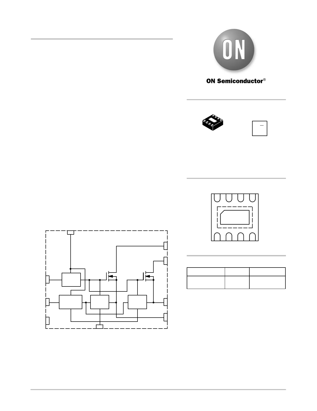
9
Vcc
http://onsemi.com
MARKING
DIAGRAM
DFN8
CASE 506AQ
43 M G
1G
43 = Specific Device Code
M = Date Code
G = Pb−Free Package
(Note: Microdot may be in either location)
PIN CONFIGURATION
1 23 4
9
1
Enable
2
Dim
3
NC
ÎÎÎÎEnaÎÎble ÎÎ
PWM
ÎÎÎÎÎÎÎAnalog/Digital
ÎÎÎÎÎÎÎControl
Current
Limit FET1
Current
ÎÎÎÎÎÎLimit FET2
4
Gnd
Figure 1. Block Diagram
6
Drain1
8 76 5
(Bottom View)
7
Drain2
ORDERING INFORMATION
Device
Package
Shipping†
NUD4301MNT1G DFN8 3000/Tape & Reel
(Pb−Free)
†For information on tape and reel specifications,
8
Source2
including part orientation and tape sizes, please
refer to our Tape and Reel Packaging Specification
Brochure, BRD8011/D.
5
Source1
This document contains information on a new product. Specifications and information
herein are subject to change without notice.
© Semiconductor Components Industries, LLC, 2006
July, 2006 − Rev. P3
1
Publication Order Number:
NUD4301/D
1 page 
Analog
Operation
3.3 V
VDIM
NUD4301
Digital
Operation
time
ILimit
ILED
time
Figure 7. Dimming Operation Curves
(Graph obtained from SPICE simulations)
Iavg
Theory of Operation
This device contains two LED current sources. Each
channel is comprised of a lateral N−channel FET controlled
by a current limit circuit that senses the voltage drop across
the Rsense resistor and compares it with an internal voltage
reference to provide the current regulation. For dimming
applications, the current limit circuit operates in
combination with the PWM signal applied to the dim pin of
the device for control purposes.
Current Limit and PWM Circuits
With a DC voltage of 3.3 volts applied to the Dim pin of
the device, the internal reference voltage of the current limit
circuit is set to 93.5 mV. The Rsense resistor is then selected
through a very simple formula: Rsense = 93.5 mV / ILED. This
allows the user to set different LED currents (between 1 mA
and 30 mA).
For dimming control, a PWM signal may be applied to the
dim pin of the device. This PWM signal can be used to
perform digital dimming.
For digital dimming, the amplitude of the PWM signal
must be 3.3 V or higher. The LED current will be
proportional to the duty cycle of the PWM signal.
For analog dimming, the input signal to the Dim pin must
be between 0 and 3.3 volts. The resulting output current will
be given by the following formula:
ILED
+
(Vdim ń35.3)
Rsense
If a PWM signal is beyond the input frequency range for
the Dim pin, a RC filter may be used to convert it to an analog
signal.
The RC filter generates an analog voltage signal, which is
proportional to the duty cycle of the PWM signal applied.
This analog signal is then used as the new reference voltage
for the current limit circuit, which compares it with the
voltage signal generated across Rsense to provide the current
regulation.
Enable
The enable circuit turns the device on when a positive
signal is applied to the enable pin. The circuit is designed to
allow low current consumption (0.1 mA typical) when the
device is disabled.
http://onsemi.com
5
5 Page | ||
| Páginas | Total 6 Páginas | |
| PDF Descargar | [ Datasheet NUD4301.PDF ] | |
Hoja de datos destacado
| Número de pieza | Descripción | Fabricantes |
| NUD4301 | Dual Low Dropout Voltage LED Driver/Current Source | ON Semiconductor |
| Número de pieza | Descripción | Fabricantes |
| SLA6805M | High Voltage 3 phase Motor Driver IC. |
Sanken |
| SDC1742 | 12- and 14-Bit Hybrid Synchro / Resolver-to-Digital Converters. |
Analog Devices |
|
DataSheet.es es una pagina web que funciona como un repositorio de manuales o hoja de datos de muchos de los productos más populares, |
| DataSheet.es | 2020 | Privacy Policy | Contacto | Buscar |