|
|
|
PDF CDB6403 Data sheet ( Hoja de datos )
| Número de pieza | CDB6403 | |
| Descripción | Echo-Cancelling Codec | |
| Fabricantes | Cirrus Logic | |
| Logotipo | ||
Hay una vista previa y un enlace de descarga de CDB6403 (archivo pdf) en la parte inferior de esta página. Total 30 Páginas | ||
|
No Preview Available !
www.DataSheet4U.com
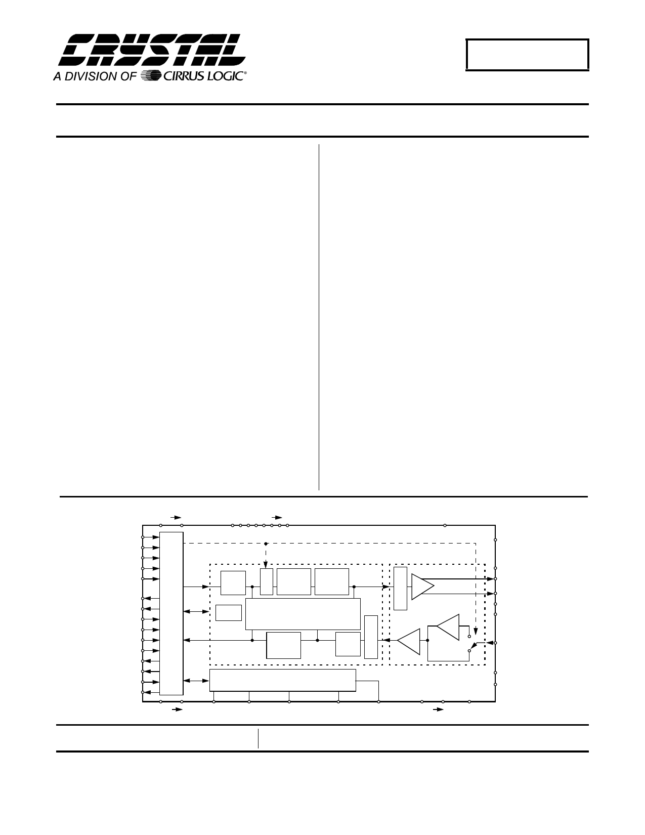
CS6403
Echo-Cancelling Codec
Features
l Applicable in:
- Digital-Cellular Hands-Free Phones
- Analog-Cellular Hands-Free Phones
- Office Speaker Phones
- Desktop & Video Teleconferencing
l Echo Cancellation
- Up to 60 dB ERLE
- 512 Tap (64 ms at 8 kHz sampling rate)
- Split Mode For Two Echo Cancellers
l Serial Data/Control Interface
l On-Chip Delta-Sigma Codec
- < 1% THD, 8 Ω Load On Output
- > 70 dB S/(N+D) on Input
- 300-3600 Hz Bandwidth (8 kHz sampling rate)
- Volume Control
- Microphone Preamp
l Automatic Gain Control (AGC)
l No Training Signals Generated
I
Description
The CS6403 is an application-specific digital signal pro-
cessor optimized for network and acoustic echo
cancellation applications. A high-quality codec is inte-
grated with the processor to provide a complete, low-
cost echo-cancellation solution.
The CS6403 is a fully independent processor that re-
quires no signal processing support to implement its
cancellation functions. Volume control, AGC, and sleep
functions are also provided.
The on-chip ADC and DAC employ over-sampling tech-
nology, which eliminates the need for complex external
anti-aliasing and reconstruction filters, further reducing
system cost.
The CS6403 has a serial interface that is compatible with
most DSPs and PCM codecs. Clock and sync lines con-
trol the transfer of serial data via the separate serial data-
in and data-out pins. Both 16-bit audio data and con-
trol/status information may be multiplexed on this serial
channel using a steering bit.
ORDERING INFORMATION
CS6403-IQ -40° to +85° C
CS6403-IL -40° to +85° C
CDB6403
44-pin TQFP
44-pin PLCC
Evaluation Board
DVDD0 1
RESERVED0 6
AVDD
CONFIG
GPIN0
GPIN1
GPIN2
GPIN3
GPOUT0
GPOUT1
SFRAME
SMASTER
UALAW
SSYNC
SCLK
SDO_1
SDI_A
SYNCOUT
DGND0
DSP
High
Pass
Control
Control
Status
A
G
C
Nonlinear
Echo
Control
Volume
Control
Echo Cancellers
A
T
Nonlinear
Echo
Control
High
Pass
T
E
N
PLL + Clock Manager
Analog I/O
A
T
T
D/A
E
N
26 dB
A/D
1 CLKIN CLKOUTSCLK_RATE0SCLK_RATE1CLK_SEL AGND0 1 NC
RESET
PVDD
SPKROUTP
SPKROUTN
PGND0
PGND1
MICIN
VCM
VREF
Preliminary Product Information
Cirrus Logic, Inc.
Crystal Semiconductor Products Division
P.O. Box 17847, Austin, Texas 78760
(512) 445 7222 FAX: (512) 445 7581
http://www.crystal.com
This document contains information for a new product.
Cirrus Logic reserves the right to modify this product without notice.
Copyright © Cirrus Logic, Inc. 1997
(All Rights Reserved)
MAR ‘96
DS192PP7
1
1 page 
CS6403
POWER CONSUMPTION (TA = 25°C; All DVDD, AVDD and PVDD = 5.0V; Signal test frequency
1kHz; Word Rate (Fs) = 8kHz; SPRKOUT outputs connected to 8Ω load; Mode 2 SCLK = 256 kHz; unless oth-
erwise specified) Full scale output.
Parameter
Symbol Min Typ Max Units
Normal Operation Power Dissipation
PD - 800 - mW
High-Impedance Output
(Note 11) PNS
-
300
- mW
RESET High
PRH
-
55
- mW
RESET High, clocks halted
(Note 12) PRNC
-
15
- mW
Powerdown Asserted in Software
PPDN
-
55
- mW
Notes: 11. SPKROUT outputs connected to 1 kΩ load.
12. RESET high, CLKIN grounded (Mode 1) or SCLK grounded (Mode 2), and CLK_SEL (PIN 15Q, 21L)
high to disable PLL.
RECOMMENDED OPERATING CONDITIONS (All voltages with respect to 0V)
DC Power Supplies:
Parameter
Ambient Operating Temperature
Symbol Min Typ Max
AVDD 4.50 5.0 5.50
DVDD
PVDD
TA -40
85
Units
V
°C
tckl tckh
CLKIN
SCLK
SYNCOUT
(Master Mode)
tpd3
SCLK & SYNCOUT Output Timing
Mode 1 - MASTER
DS192PP6
5
5 Page 
CS6403
Analog Interface
The codec block provides an analog-to-digital
converter (ADC) and a digital-to-analog con-
verter that can be connected directly to a
microphone and a speaker, respectively.
The output of the microphone should be low-
pass filtered, then AC-coupled to the audio input,
MICIN. A 26 dB gain stage is included in the
CS6403 at the ADC input to amplify the micro-
phone signal. However, this gain stage may be
bypassed in modes in which a line-level source
is connected to the CS6403 instead of a micro-
phone. The CS6403 also includes a speaker
driver, which can drive an 8Ω speaker directly,
or alternatively, it can drive a high-impedance
differential input on an external amplifier.
With the 26 dB gain stage on, the fullscale input
for the MICIN pin is 100mV peak-to-peak. Any
signal over 100mV peak-to-peak will clip the in-
put to the ADC. With the gain stage off, a 2V
peak-to-peak signal is the maximum allowed.
The fullscale output voltage from the DAC is
1.75V peak-to-peak single-ended, or 3.5V peak-
to-peak differentially.
SCLK
000
001
010
011
100
101
110
111
Clock Rate I/O
256 kHz I
undefined
1.024 MHz I
2.048 MHz I
mode
slave
slave
slave
undefined
undefined
undefined
2.048 MHz O master
It is very important to not clip signals anywhere
in the system. An echo canceller can only re-
move echo that passes through a linear, time
invariant path. Echo that passes through a non-
linearity (like clipping) will not be removed by
the echo canceller.
Both the DAC and ADC paths are bandlimited
as a function of sampling rate. At a sampling
rate of 8 kHz, the paths are limited to 0-
3600 Hz.
Synchronous Serial Interface
The Synchronous Serial Interface (SSI) provides
a data and control interface to the CS6403. The
SSI can be connected to an external network
codec for applications like speakerphones or to a
DSP for high-end applications like video tele-
conferencing.
Depending on the state of the SMASTER
(PIN 42Q, 4L) pin at RESET, the CS6403 can
operate as either a system timing master or slave.
As a master, the serial clock pin (SCLK) is an
output. As a system timing slave, SCLK must
be driven by an external source. When SMAS-
TER is high, the SCLK output frequency is a
fixed 2.048 MHz derived from the 8.192 MHz
crystal oscillator connected across CLKIN and
CLKOUT. When SMASTER is low, internal
timing is generated by the Phase Locked Loop
(PLL), which uses SCLK’s input as a timing ref-
erence, so no external crystal is necessary. In
slave timing mode, SCLK can be driven at 256
kHz, 1.024 MHz, or 2.048 MHz. The CS6403 is
informed of the SCLK rate via the
SCLK_RATE0 (PIN 29Q, 35L) and
SCLK_RATE1 (PIN 30Q, 36L) pins.
Table 1 shows the various options for SCLK.
Table 1. Clock Options
DS192PP6
11
11 Page | ||
| Páginas | Total 30 Páginas | |
| PDF Descargar | [ Datasheet CDB6403.PDF ] | |
Hoja de datos destacado
| Número de pieza | Descripción | Fabricantes |
| CDB6403 | Echo-Cancelling Codec | Cirrus Logic |
| Número de pieza | Descripción | Fabricantes |
| SLA6805M | High Voltage 3 phase Motor Driver IC. |
Sanken |
| SDC1742 | 12- and 14-Bit Hybrid Synchro / Resolver-to-Digital Converters. |
Analog Devices |
|
DataSheet.es es una pagina web que funciona como un repositorio de manuales o hoja de datos de muchos de los productos más populares, |
| DataSheet.es | 2020 | Privacy Policy | Contacto | Buscar |