|
|
|
PDF ATAR092-C Data sheet ( Hoja de datos )
| Número de pieza | ATAR092-C | |
| Descripción | (ATAR092-C / ATAR892-C) Low-current Microcontroller | |
| Fabricantes | ATMEL Corporation | |
| Logotipo | ||
Hay una vista previa y un enlace de descarga de ATAR092-C (archivo pdf) en la parte inferior de esta página. Total 30 Páginas | ||
|
No Preview Available !
Features
• Extended Temperature Range for High Temperature up to 105°C
• 4-Kbyte ROM, 256 × 4-bit RAM
• 16 Bi-directional I/Os
• Up to 7 External/Internal Interrupt Sources
• Multifunction Timer/Counter with
– IR Remote Control Carrier Generator
– Bi-phase, Manchester and Pulse-width Modulator and Demodulator
– Phase Control Function
• Programmable System Clock with Prescaler and Five Different Clock Sources
• Wide Supply-voltage Range (1.8V to 6.5V)
• Very Low Sleep Current (< 1 µA)
• 32 × 16-bit EEPROM (ATAR892-C only)
• Synchronous Serial Interface (2-wire, 3-wire)
• Watchdog, POR and Brown-out Function
• Voltage Monitoring Inclusive Lo_BAT Detect
• Flash Controller ATAM893 Available (SSO20)
1. Description
The ATAR092-C and ATAR892-C are members of Atmel’s family of 4-bit single-chip
microcontrollers. They offer the highest integration for IR and RF data communication,
remote-control and phase-control applications. The ATAR092-C and ATAR892-C are
suitable as transmitters as well as receivers. They contain ROM, RAM, parallel I/O
ports, two 8-bit programmable multifunction timer/counters with modulator and
www.DataSheet4U.com
demodulator function, voltage supervision, interval timer with watchdog function and a
sophisticated on-chip clock generation with external clock input, integrated RC-,
32-kHz crystal- and 4-MHz crystal-oscillators. The ATAR892-C has an additional
EEPROM as a second chip in one package.
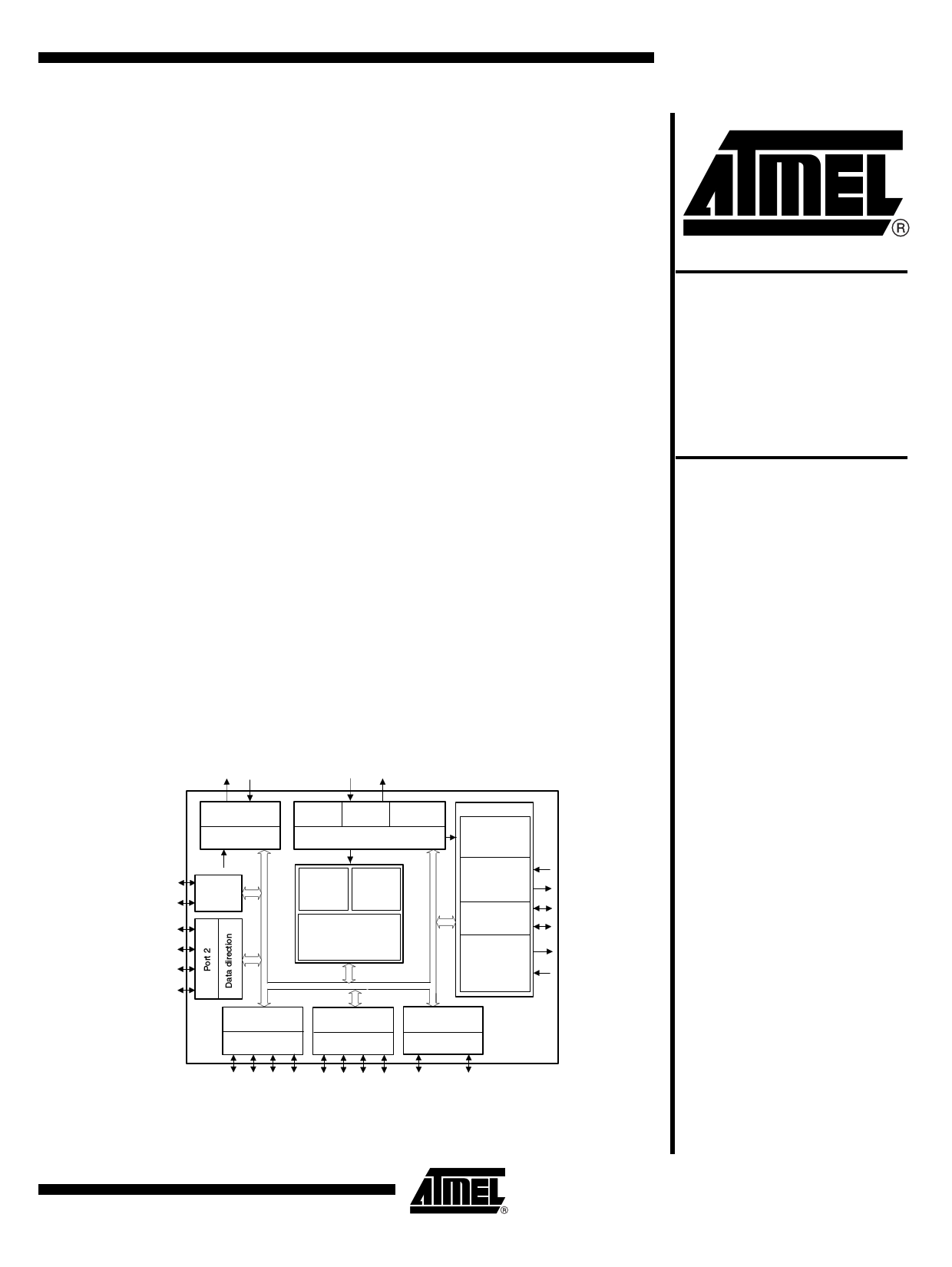
Figure 1-1. Block Diagram
VSS VDD
OSC1 OSC2
BP10
BP13
BP20/NTE
BP21
BP22
BP23
Brown-out protect.
RESET
Voltage monitor
External input
VMI
Port 1
RC
Crystal
External
oscillators oscillators clock input
Clock management
ROM
4 K x 8 bit
RAM
256 x 4 bit
MARC4
4-bit CPU core
I/O bus
UTCM
Timer 1
interval- and
watchdog timer
Timer 2
T2I
8/12-bit timer
with modulator
SSI
Serial interface
T2O
SD
SC
Timer 3
8-bit
timer/counter
with modulator
and demodulator
T3O
T3I
Data direction +
alternate function
Port 4
Data direction +
interrupt control
Port 5
Data direction +
alternate function
Port 6
BP40 BP42
INT3 T2O
BP50
INT6
BP52
INT1
SC BP41 BP43
BP51
BP53
VMI INT3
INT6
INT1
T2I SD
BP60
T3O
BP63
T3I
Low-current
Microcontroller
for Wireless
Communication
ATAR092-C
ATAR892-C
4593D–4BMCU–05/06
1 page 
ATAR092-C/ATAR892-C
4.2.2.2
Return Stack
The 12-bit wide return stack is addressed by the return stack pointer (RP). It is used for storing
return addresses of subroutines, interrupt routines and for keeping loop index counts. The return
stack can also be used as a temporary storage area.
The MARC4 instruction set supports the exchange of data between the top elements of the
expression stack and the return stack. The two stacks within the RAM have a user definable
location and maximum depth.
Figure 4-3. RAM Map
RAM
(256 x 4-bit)
Autosleep
FCh
X
Y
SP TOS-1
RP
04h
00h
Expression stack
30
FFh TOS
Global
variables
TOS-1
TOS-2
SP
4-bit
Expression
stack
Return
stack
Global
07h variables
03h
Return stack
11 0
RP
12-bit
4.2.3
Registers
The MARC4 controller has seven programmable registers and one condition code register. They
are shown in the following programming model (Figure 4-4 on page 6).
4.2.3.1
Program Counter (PC)
The program counter is a 12-bit register which contains the address of the next instruction to be
fetched from ROM. Instructions currently being executed are decoded in the instruction decoder
to determine the internal micro-operations. For linear code (no calls or branches) the program
counter is incremented with every instruction cycle. If a branch-, call-, return-instruction or an
interrupt is executed, the program counter is loaded with a new address. The program counter is
also used with the table instruction to fetch 8-bit wide ROM constants.
4593D–4BMCU–05/06
5
5 Page 
ATAR092-C/ATAR892-C
Figure 4-7. Reset Configuration
VDD
Pull-up
NRST
CL Reset
timer
res
CL = SYSCL/4
Power-on
reset
Brown-out
detection
Watch-
dog res
Internal
reset
VDD
VSS
VDD
VSS
CWD
Ext. clock
supervisor
ExIn
4.3.1
Power-on Reset and Brown-out Detection
The ATAR092-C/ATAR892-C have a fully integrated power-on reset and brown-out detection
circuitry. For reset generation no external components are needed.
These circuits ensure that the core is held in the reset state until the minimum operating supply
voltage has been reached. A reset condition will also be generated should the supply voltage
drop momentarily below the minimum operating level except when a power down mode is acti-
vated (the core is in SLEEP mode and the peripheral clock is stopped). In this power-down
mode the brown-out detection is disabled. Two values for the brown-out voltage threshold are
programmable via the BOT bit in the SC register.
A power-on reset pulse is generated by a VDD rise across the default BOT voltage level (1.7V). A
brown-out reset pulse is generated when VDD falls below the brown-out voltage threshold. Two
values for the brown-out voltage threshold are programmable via the BOT bit in the SC register.
When the controller runs in the upper supply voltage range with a high system clock frequency,
the high threshold must be used. When it runs with a lower system clock frequency, the low
threshold and a wider supply voltage range may be chosen. For further details, see the electrical
specification and the SC register description for BOT programming.
4593D–4BMCU–05/06
11
11 Page | ||
| Páginas | Total 30 Páginas | |
| PDF Descargar | [ Datasheet ATAR092-C.PDF ] | |
Hoja de datos destacado
| Número de pieza | Descripción | Fabricantes |
| ATAR092-C | (ATAR092-C / ATAR892-C) Low-current Microcontroller | ATMEL Corporation |
| ATAR092-D | Low-current Microcontroller | ATMEL Corporation |
| Número de pieza | Descripción | Fabricantes |
| SLA6805M | High Voltage 3 phase Motor Driver IC. |
Sanken |
| SDC1742 | 12- and 14-Bit Hybrid Synchro / Resolver-to-Digital Converters. |
Analog Devices |
|
DataSheet.es es una pagina web que funciona como un repositorio de manuales o hoja de datos de muchos de los productos más populares, |
| DataSheet.es | 2020 | Privacy Policy | Contacto | Buscar |