|
|
|
PDF H3CR-A Data sheet ( Hoja de datos )
| Número de pieza | H3CR-A | |
| Descripción | Timer | |
| Fabricantes | Omron | |
| Logotipo | ||
Hay una vista previa y un enlace de descarga de H3CR-A (archivo pdf) en la parte inferior de esta página. Total 26 Páginas | ||
|
No Preview Available !
R
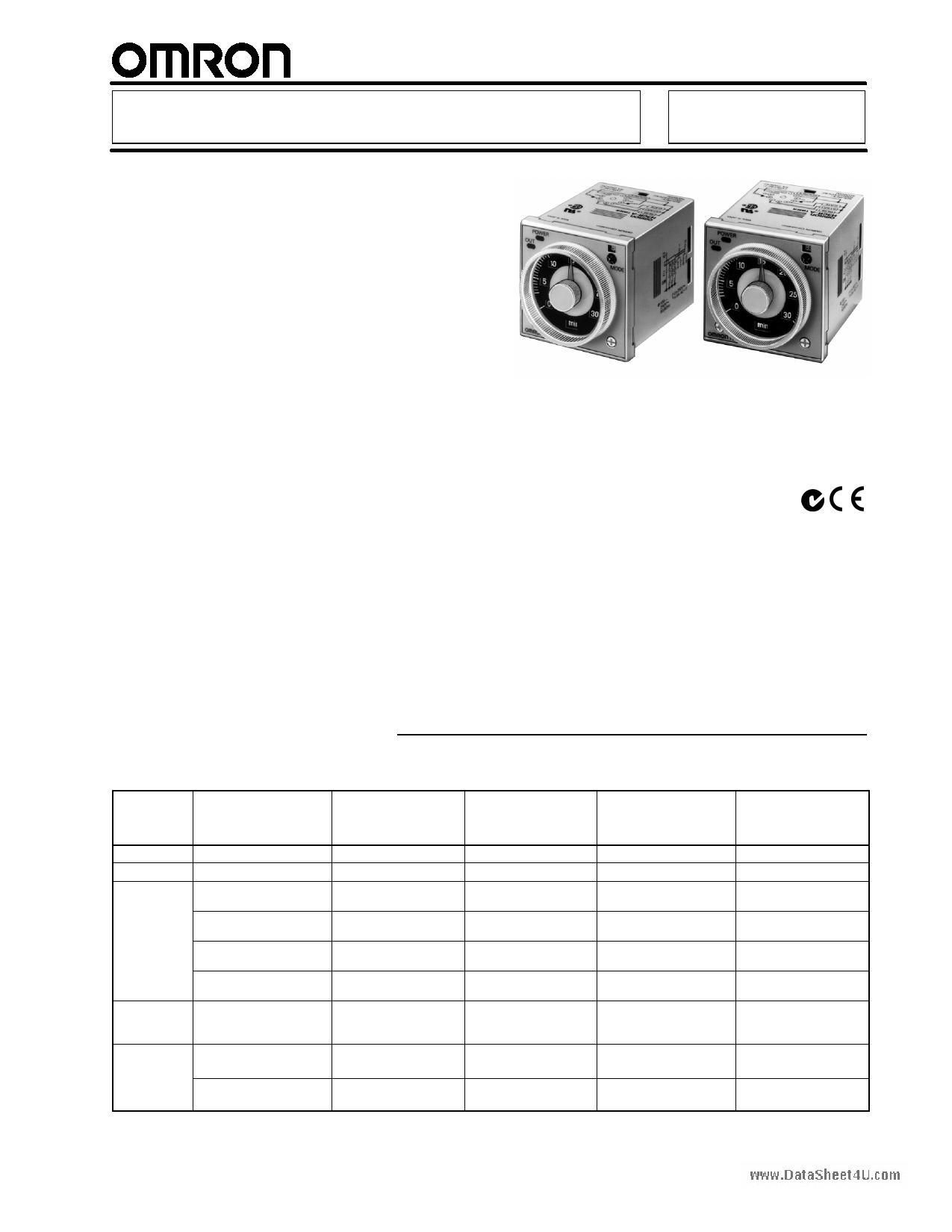
Solid-State Timer
H3CR-A
1/16 DIN Analog-Set Timer with Many
Time Ranges, Operating Modes and
Wide Supply Voltage Range
H Field-selectable time ranges from 0.05
second to 300 hours or 0.1 second to
600 hours
Hwww.DataSheet4U.com Select 2-, 4-, or 6-function models to
handle most applications
H Wide range AC/DC supply voltage
models (AC100-240/DC100-125 or
AC24-48/DC12-24)
H PNP input now available
H Short, 80 mm (3.15 inch) panel
mounting depth with socket allows
space-efficient control panel design
H Choice of light gray, medium gray, or
black panel covers to match panel
aesthetics
H UL, CSA, CE approved
RC
Ordering Information
J TIMERS
Timing
function
Time range
Terminal form
Part number/
contact output
Part number/
transistor
output
Part number/
time-limiting
and
instantaneous
contact output
ON-Delay, Repeat cycle
(B, B2), Signal ON/OFF
delay, Signal OFF-delay,
Interval
0.05 s to 300 hr
11-pin round
H3CR-A
AC100-240/DC100-125
H3CR-A
AC24-48/DC12-48
H3CR-AP
AC100-240/DC100-125
H3CR-AP
AC24-48/DC12-48
H3CR-AS
AC24-48/DC12-48
—
—
Signal ON/OFF-
delay, One-shot
Signal ON/OFF-
delay, One-shot
ON-Delay, Repeat cycle
ON, Interval, One-shot
0.05 s to 300 hr
11-pin round
H3CR-A-300
AC100-240/DC100-125
H3CR-A-300
AC24-48/DC12-48
—
0.1 s to 600 hr
11-pin round
H3CR-A-301
AC100-240/DC100-125
H3CR-A-301
AC24-48/DC12-48
—
0.05 s to 300 hr
8-pin round
H3CR-A8
AC100-240/DC100-125
H3CR-A8
AC24-48/DC12-48
—
———
— — H3CR-A8S
AC24-48/DC12-48
— — H3CR-A8E
AC100-240/DC100-125
— — H3CR-A8E
AC24-48/DC12-48
ON-Delay, Repeat cycle
ON, Interval, One-shot
0.1 s to 600 hr
8-pin round
H3CR-A8-301
AC100-240/DC100-125
H3CR-A8-301
AC24-48/DC12-48
—
—
—
—
—
1
1 page 
H3CR-A
H3CR-A
Item
Reset time
Reset voltage
Resetting system
Indicators
Material
Mounting method
Connection
Weight
Approved standards
www.DataSheet4U.com
Ambient
temperature
Operating
Storage
Ambient
humidity
Operating
Variation due to voltage
change
Variation due to
temperature change
Insulaton resistance
Vibration resistance
Shock resistance
Static immunity
Dielectric strength
Impulse withstand voltage
EMC
H3CR-A/A8
H3CR-AP
H3CR-A8E
H3CR-AS/A8S
Min. power-opening time: 0.1 s max.
Min. pulse width: 0.05 s (H3CR-A/-AS)
10% max. of rated voltage
Power OFF, external, self resetting (11-pin models); Power OFF (8-pin models)
Power ON indicator (green LED), Output ON indicator (orange LED)
Plastic case (light gray Munsell 5Y7/1) and knob (clear)
DIN track mounting, surface mounting, and flush mounting
11-pin (H3CR-A)
8-pin (H3CR-A8)
11-pin
8-pin
11-pin (H3CR-AS)
8-pin (H3CR-A8S)
Approx. 90 g (3.17 oz)
UL508, CSA C22.2 No.14, NK, Lloyds
Conforms to EN61812-1 (VDE0435/P2021), IEC60664-1 (VDE0110) 4kV/2, EN60947-5-1 (contact
output), and EN60947-5-2 (non-contact output).
--10°C to 55°C (14°F to 131°F) with no icing
--25°C to 65°C (-13°F to 149°F) with no icing
35% to 85%
±0.2% FS max. (±0.2% ±10 ms max. in a range of 1.2 s)
±1% FS max. (±1% ±10 ms max. in a range of 1.2 s)
100 MΩ min. (at 500 VDC)
Destruction: 10 to 55 Hz with 0.75-mm double amplitude each in 3 directions for 2 hours each
Malfunction: 10 to 55 Hz with 0.5-mm double amplitude each in 3 directions for 10 minutes each
Destruction: 1,000 m/s2 (approx. 100G) 3 times each in 6 directions
Malfunction: 100 m/s2 (approx. 10G) 3 times each in 6 directions
Malfunction: 8 kV
Destruction: 15 kV
2,000 VAC (1,000 VAC for H3CR-AjS), 50/60 Hz for 1 min between current-carrying metal parts and
exposed non-current-carrying metal parts
2,000 VAC (1,000 VAC for H3CR-AjS), 50/60 Hz for 1 min between control output terminals and
operating circuit
2,000 VAC, 50/60 Hz for 1 min between contacts of different polarities
1,000 VAC, 50/60 Hz for 1 min between contacts not located next to each other
2,000 VAC, 50/60 Hz for 1 min between input and control output terminals and operation circuit
3 kV (between power terminals) for 100 to 240 VAC/100 to 125 VDC; 1 kV for 24 to 48 VAC/12 to 48 VDC
4.5 kV (between current-carrying terminal and exposed non-current-carrying metal parts) for 100 to
240 VAC/100 to 125 VDC; 1.5 kV for 24 to 48 VAC/12 to 48 VDC and 24 to 48 VAC/VDC
(EMI)
Emission enclosure:
Emission AC mains:
(EMS)
Immunity ESD:
EN50081-2
EN55011 Group 1 class A
EN55011 Group 1 class A
EN50082-2
EN61000-4-2: 4 kV contact discharge (level 2)
8 kV air discharge (level 3)
Immunity RF-interference from AM radio waves: ENV50140: 10 V/m (80 MHz to 1 GHz) (level 3)
Immunity RF-interference from pulse-modulated radio waves: ENV50204: 10 V/m (900±5 MHz)
(level 3)
Degree of protection
Life
expectancy
Mechanical
Electrical
Immunity conducted disturbance:
ENV50141: 10 V (0.15 to 80 MHz) (level 3)
Immunity burst:
EN61000-4-4: 2 kV power-line (level 3)
2 kV I/O signal-line (level 4)
Immunity surge:
EN61000-4-5: 1 kV line to line
2 kV line to ground (level 3)
IP40 (front face)
20,000,000 operations min. (under no load at 1,800 operations/h)
100,000 operations min. (5 A at 250 VAC, resistive load at 1,800 operations/h)
5
5 Page 
H3CR-A
H3CR-A
B/B2 Mode: Repeat Cycle
The repeat cycle operation in the B and B2 modes can be
effectively applied to lamp or buzzer (ON and OFF) alarms or the
monitoring of an intermittent operation with a display.
1. Power-ON Start/Power-OFF Reset
The start terminals are connected. Timing starts when power is
applied. The output relay or transistor operates according to
mode B (OFF/ON/OFF pattern) or mode B2 (ON/OFF/ON
pattern), whichever is set. The cycle repeats until a reset input is
applied or power is disconnected.
Power (2 and 10)
Start (2 and 6)
Control output: NC (8 and 11)
www.DataSheet4U.com
NC (1 and 4)
Control output: NO (9 and 11)
NO (1 and 3)
Power indicator
Flashing
Externally short-circuited
C Mode: Signal ON/OFF-delay
The Signal ON-/OFF-delay operation (C mode) is useful for the
control of distribution of products on a production line into boxes
by the specified number or time.
1. Power-ON Start/Instantaneous Operation/Time-limit Reset
The timing cycle starts when power is applied. When the timer
reaches set point, the output status changes and holds that
status until power turns OFF to reset the timer. Minimum reset
time is 0.1 second.
Power (2 and 10)
Start (2 and 6)
Control output: NC (8 and 11)
NC (1 and 4)
Control output: NO (9 and 11)
NO (1 and 3)
Start signal (NC to NO)
Power
supply
2. Signal Start/Signal Reset
If there is an abnormal signal, flashing starts. When the abnormal
condition is restored, a reset signal stops the display flashing.
Power is continuously applied. The ON/OFF cycle is initiated at
the leading edge of the start input.
In Mode B the output relay or transistor will be OFF for the set
time and then ON for the set time, creating an operation pattern
of OFF/ON/OFF.
In Mode B2 the output relay or transistor will turn ON for the set
time and then OFF for the set time, creating an operation pattern
of ON/OFF/ON. This cycle will be repeated until a reset input is
applied or power is disconnected. The minimum signal input time
is 0.05 second.
Power (2 and 10)
Start (2 and 6)
Reset (2 and 7)
Control output: NC (8 and 11)
NC (1 and 4)
Control output: NO (9 and 11)
NO (1 and 3)
Power indicator
Lit
Start signal
Reset signal
Flashing
Lit
Power
supply
2. Signal-ON-OFF Start/Instantaneous Operation/Time-limit
Reset
Power is continuously applied. The first timing cycle begins when
the input signal is applied, the second when it is removed. The
output relay or transistor is energized when the lapsed time from
the first timing cycle equals the set point. The output remains
energized until the lapsed time of the second timing cycle equals
the set point. The minimum signal input time is 0.05 second.
Power (2 and 10)
Start (2 and 6)
Control output: NC (8 and 11)
NC (1 and 4)
Control output: NO (9 and 11)
NO (1 and 3)
Power indicator
Start signal
(The operation starts with the signal ON or OFF)
Power
supply
(Power continuously supplied)
Power
supply
(Power continuously supplied)
11
11 Page | ||
| Páginas | Total 26 Páginas | |
| PDF Descargar | [ Datasheet H3CR-A.PDF ] | |
Hoja de datos destacado
| Número de pieza | Descripción | Fabricantes |
| H3CR-A | Timer | Omron |
| Número de pieza | Descripción | Fabricantes |
| SLA6805M | High Voltage 3 phase Motor Driver IC. |
Sanken |
| SDC1742 | 12- and 14-Bit Hybrid Synchro / Resolver-to-Digital Converters. |
Analog Devices |
|
DataSheet.es es una pagina web que funciona como un repositorio de manuales o hoja de datos de muchos de los productos más populares, |
| DataSheet.es | 2020 | Privacy Policy | Contacto | Buscar |