|
|
|
PDF ADP1612 Data sheet ( Hoja de datos )
| Número de pieza | ADP1612 | |
| Descripción | (ADP1612 / ADP1613) 650 KHz /1.3 MHz Step-Up PWM DC-to-DC Switching Converter | |
| Fabricantes | Analog Devices | |
| Logotipo | ||
Hay una vista previa y un enlace de descarga de ADP1612 (archivo pdf) en la parte inferior de esta página. Total 28 Páginas | ||
|
No Preview Available !
www.DataSheet4U.com
650 kHz /1.3 MHz Step-Up
PWM DC-to-DC Switching Converters
ADP1612/ADP1613
FEATURES
Current limit
1.4 A for the ADP1612
2.0 A for the ADP 1613
Minimum input voltage
1.8 V for the ADP1612
2.5 V for the ADP1613
Pin-selectable 650 kHz or 1.3 MHz PWM frequency
Adjustable output voltage up to 20 V
Adjustable soft start
Undervoltage lockout
Thermal shutdown
8-lead MSOP
APPLICATIONS
TFT LCD bias supplies
Portable applications
Industrial/instrumentation equipment
TYPICAL APPLICATION CIRCUIT
L1
ADP1612/
VIN ADP1613
6 VIN
SW 5
ON
OFF
3 EN
CIN 1.3MHz
650kHz
7 FREQ
(DEFAULT)
FB 2
8 SS
COMP 1
CSS
GND
4
D1 VOUT
R1
R2
RCOMP
CCOMP
COUT
Figure 1. Step-Up Regulator Configuration
GENERAL DESCRIPTION
The ADP1612/ADP1613 are step-up dc-to-dc switching con-
verters with an integrated power switch capable of providing
an output voltage as high as 20 V. With a package height of less
than 1.1 mm, the ADP1612/ADP1613 are optimal for space-
constrained applications such as portable devices or thin film
transistor (TFT) liquid crystal displays (LCDs).
The ADP1612/ADP1613 operate in current mode pulse-width
modulation (PWM) with up to 94% efficiency. Adjustable
soft start prevents inrush currents when the part is enabled.
The pin-selectable switching frequency and PWM current-mode
architecture allow for excellent transient response, easy noise
filtering, and the use of small, cost-saving external inductors
and capacitors. Other key features include undervoltage lockout
(UVLO), thermal shutdown (TSD), and logic controlled enable.
The ADP1612/ADP1613 are available in the lead-free
8-lead MSOP.
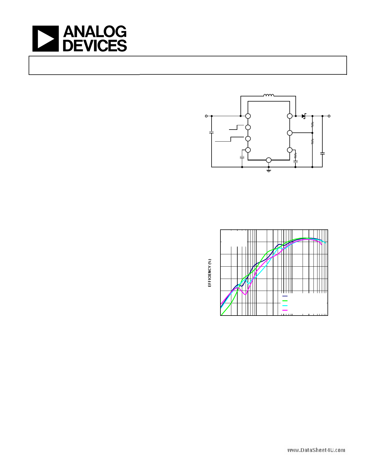
100
VIN = 5V
90
fSW = 1.3MHz
TA = 25°C
80
70
60
50
ADP1612, VOUT = 12V
40
ADP1612, VOUT = 15V
ADP1613, VOUT = 12V
ADP1613, VOUT = 15V
30
1 10 100 1k
LOAD CURRENT (mA)
Figure 2. ADP1612/ADP1613 Efficiency for Various Output Voltages
Rev. 0
Information furnished by Analog Devices is believed to be accurate and reliable. However, no
responsibility is assumed by Analog Devices for its use, nor for any infringements of patents or other
rights of third parties that may result from its use. Specifications subject to change without notice. No
license is granted by implication or otherwise under any patent or patent rights of Analog Devices.
Trademarksandregisteredtrademarksarethepropertyoftheirrespectiveowners.
One Technology Way, P.O. Box 9106, Norwood, MA 02062-9106, U.S.A.
Tel: 781.329.4700
www.analog.com
Fax: 781.461.3113
©2009 Analog Devices, Inc. All rights reserved.
1 page 
www.DataSheet4U.com
PIN CONFIGURATION AND FUNCTION DESCRIPTIONS
ADP1612/ADP1613
COMP 1
FB 2
EN 3
GND 4
ADP1612/
ADP1613
TOP VIEW
(Not to Scale)
8 SS
7 FREQ
6 VIN
5 SW
Figure 3. Pin Configuration
Table 4. Pin Function Descriptions
Pin No. Mnemonic Description
1
COMP
Compensation Input. Connect a series resistor-capacitor network from COMP to GND to compensate the regulator.
2 FB
Output Voltage Feedback Input. Connect a resistive voltage divider from the output voltage to FB to set the
regulator output voltage.
3 EN
Enable Input. Drive EN low to shut down the regulator; drive EN high to turn on the regulator.
4 GND
Ground.
5 SW
Switching Output. Connect the power inductor from the input voltage to SW and connect the external rectifier
from SW to the output voltage to complete the step-up converter.
6 VIN
Main Power Supply Input. VIN powers the ADP1612/ADP1613 internal circuitry. Connect VIN to the input source
voltage. Bypass VIN to GND with a 10 μF or greater capacitor as close to the ADP1612/ADP1613 as possible.
7 FREQ Frequency Setting Input. FREQ controls the switching frequency. Connect FREQ to GND to program the oscillator
to 650 kHz, or connect FREQ to VIN to program it to 1.3 MHz. If FREQ is left floating, the part defaults to 650 kHz.
8 SS
Soft Start Timing Capacitor Input. A capacitor connected from SS to GND brings up the output slowly at power-
up and reduces inrush current.
Rev. 0 | Page 5 of 28
5 Page 
www.DataSheet4U.com
ADP1612/ADP1613
THEORY OF OPERATION
VIN L1
CIN
VIN
6
>1.6V
<0.3V
FREQ
7
+
VIN D +
COMPARATOR
VOUT
R1
FB
2
ERROR
AMPLIFIER
PWM
COMPARATOR
R2 VBG
COMP
1
UVLO
COMPARATOR
VIN
RCOMP
CCOMP
CSS
SS
8
VSS
5µA
UVLOREF
TSD
COMPARATOR
TSENSE
SOFT
START
TREF
DREF
OSCILLATOR
RESET
S
Q
R
BG
A
CURRENT
SENSING
5µA
DRIVER
BAND GAP
1.1MΩ
ADP1612/AD1613
AGND
SW
5
N1
D1
VOUT
COUT
AGND
3
EN >1.6V
<0.3V
4
GND
Figure 34. Block Diagram with Step-Up Regulator Application Circuit
The ADP1612/ADP1613 current-mode step-up switching
converters boost a 1.8 V to 5.5 V input voltage to an output
voltage as high as 20 V. The internal switch allows a high
output current, and the high 650 kHz/1.3 MHz switching
frequency allows for the use of tiny external components.
The switch current is monitored on a pulse-by-pulse basis to
limit it to 1.4 A typical (ADP1612) or 2.0 A typical (ADP1613).
CURRENT-MODE PWM OPERATION
The ADP1612/ADP1613 utilize a current-mode PWM control
scheme to regulate the output voltage over all load conditions.
The output voltage is monitored at FB through a resistive voltage
divider. The voltage at FB is compared to the internal 1.235 V
reference by the internal transconductance error amplifier to
create an error voltage at COMP. The switch current is internally
measured and added to the stabilizing ramp. The resulting sum
is compared to the error voltage at COMP to control the PWM
modulator. This current-mode regulation system allows fast
transient response, while maintaining a stable output voltage.
By selecting the proper resistor-capacitor network from COMP
to GND, the regulator response is optimized for a wide range of
input voltages, output voltages, and load conditions.
FREQUENCY SELECTION
The frequency of the ADP1612/ADP1613 is pin-selectable
to operate at either 650 kHz to optimize the regulator for high
efficiency or at 1.3 MHz for use with small external components.
If FREQ is left floating, the part defaults to 650 kHz. Connect
FREQ to GND for 650 kHz operation or connect FREQ to VIN
for 1.3 MHz operation. When connected to VIN for 1.3 MHz
operation, an additional 5 μA, typical, of quiescent current is
active. This current is turned off when the part is shutdown.
SOFT START
To prevent input inrush current to the converter when the part is
enabled, connect a capacitor from SS to GND to set the soft start
period. Once the ADP1612/ADP1613 are turned on, SS sources
5 μA, typical, to the soft start capacitor (CSS) until it reaches
1.2 V at startup. As the soft start capacitor charges, it limits the
peak current allowed by the part. By slowly charging the soft
start capacitor, the input current ramps slowly to prevent it
from overshooting excessively at startup. When the ADP1612/
ADP1613 are in shutdown mode (EN ≤ 0.3 V), a thermal shut-
down event occurs, or the input voltage is below the falling
undervoltage lockout voltage, SS is internally shorted to GND
to discharge the soft start capacitor.
Rev. 0 | Page 11 of 28
11 Page | ||
| Páginas | Total 28 Páginas | |
| PDF Descargar | [ Datasheet ADP1612.PDF ] | |
Hoja de datos destacado
| Número de pieza | Descripción | Fabricantes |
| ADP161 | CMOS Linear Regulators | Analog Devices |
| ADP1610 | 1.2 MHz DC-DC Step-Up Switching Converter | Analog Devices |
| ADP1611 | 1.2 MHz Step-Up DC-to-DC Switching Converter | Analog Devices |
| ADP1612 | (ADP1612 / ADP1613) 650 KHz /1.3 MHz Step-Up PWM DC-to-DC Switching Converter | Analog Devices |
| Número de pieza | Descripción | Fabricantes |
| SLA6805M | High Voltage 3 phase Motor Driver IC. |
Sanken |
| SDC1742 | 12- and 14-Bit Hybrid Synchro / Resolver-to-Digital Converters. |
Analog Devices |
|
DataSheet.es es una pagina web que funciona como un repositorio de manuales o hoja de datos de muchos de los productos más populares, |
| DataSheet.es | 2020 | Privacy Policy | Contacto | Buscar |