|
|
|
PDF ISL12022MA Data sheet ( Hoja de datos )
| Número de pieza | ISL12022MA | |
| Descripción | Low Power RTC | |
| Fabricantes | Intersil Corporation | |
| Logotipo | ||
Hay una vista previa y un enlace de descarga de ISL12022MA (archivo pdf) en la parte inferior de esta página. Total 29 Páginas | ||
|
No Preview Available !
Low Power RTC with Battery Backed SRAM,
Integrated ±5ppm Temperature Compensation and
Auto Daylight Saving
ISL12022MA
The ISL12022MA device is a low power real time clock
(RTC) with an embedded temperature sensor and
crystal. Device functions include oscillator compensation,
clock/calendar, power fail and low battery monitors,
brownout indicator, one-time, periodic or polled alarms,
intelligent battery backup switching, Battery Reseal™
function and 128 bytes of battery-backed user SRAM.
The device is offered in a 20 Ld SOIC module that
contains the RTC and an embedded 32.768kHz quartz
crystal. The calibrated oscillator provides less than ±5ppm
drift over the full -40°C to +85°C temperature range.
The RTC tracks time with separate registers for hours,
minutes, and seconds. The calendar registers track date,
month, year and day of the week and are accurate
through 2099, with automatic leap year correction.
Daylight Savings time adjustment is done automatically,
using parameters entered by the user. Power fail and
battery monitors offer user-selectable trip levels. The
time stamp function records the time and date of
switchover from VDD to VBAT power, and also from VBAT
to VDD power.
The ISL12022MA features enhanced immunity to ESD
per the IEC61000-4-2 standard, and also provides
improved resistance to system leakage related to
environmental moisture.
Related Literature
• See TB484 “ISL12022MA Enhanced RTC Module”
• See AN1549 “Addressing Power Issues in Real Time
Clock Applications”
Features
• Embedded 32.768kHz Quartz Crystal in the Package
• 20 Ld SOIC Package (for DFN version, refer to the
ISL12020M)
• Calendar
• On-chip Oscillator Temperature Compensation
• 10-bit Digital Temperature Sensor Output
• 15 Selectable Frequency Outputs
• Interrupt for Alarm or 15 Selectable Frequency
Outputs
• Automatic Backup to Battery or Supercapacitor
• VDD and Battery Status Monitors
• Battery Reseal™ Function to Extend Battery Shelf Life
• Power Status Brownout Monitor
• Time Stamp for Battery Switchover
• 128 Bytes Battery-Backed User SRAM
• I2C-Bus™
• RoHS Compliant
Applications
• Utility Meters
• POS Equipment
• Printers and Copiers
• Digital Cameras
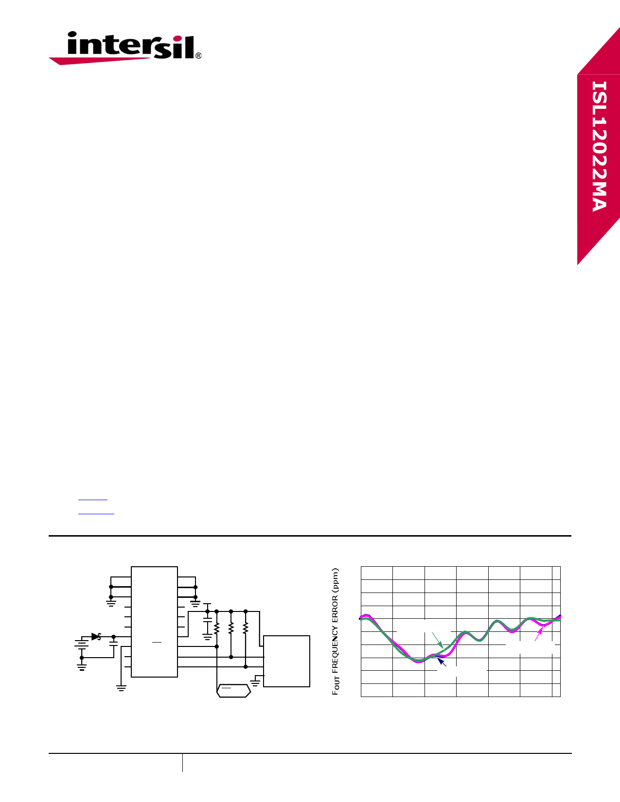
Typical Application Circuit
1 GND
GND 20
2 GND
GND 19
3 GND
4 GND
GND 18
NC 17
3.3V
SCHOTTKY DIODE
BAT54
BATTERY
3.0V
C2
0.1µF
5 NC
6 NC
7 VBAT
8 GND
9 NC
NC 16
NC 15
VDD 14
IRQ/FOUT 13
SCL 12
C1
0.1µF
R1 R2 R3
10k 10k 10k
10 NC
SDA 11
ISL12022MA
VDO
SCL MCU
SDA INTERFACE
GND
IRQ/FOUT
Performance Curve
5 OSCILLATOR ERROR vs TEMPERATURE
4
3
2
1
0 VBAT = 5.5V
-1 VDD = 2.7V
-2
-3 VDD = 3.3V
-4
-5
-40
-20
0 20 40
TEMPERATURE (°C)
60
80
July 9, 2010
FN7575.1
www.DataSheet.in
1 CAUTION: These devices are sensitive to electrostatic discharge; follow proper IC Handling Procedures.
1-888-INTERSIL or 1-888-468-3774 | Intersil (and design) is a registered trademark of Intersil Americas Inc.
I2C Bus is a registered trademark owned by NXP Semiconductors Netherlands, B.V.
Copyright Intersil Americas Inc. 2010. All Rights Reserved.
All other trademarks mentioned are the property of their respective owners.
1 page 
ISL12022MA
Absolute Maximum Ratings
Voltage on VDD, VBAT and IRQ/FOUT pins
(Respect to Ground) . . . . . . . . . . . . . . . . . -0.3V to 6.0V
Voltage on SCL and SDA pins
(Respect to Ground) . . . . . . . . . . . . -0.3V to VDD + 0.3V
ESD Rating
Human Body Model (Per JESD22-A114F) . . . . . . . . . . >3kV
Machine Model (Per JESD22-A115B) . . . . . . . . . . . . >300V
Charge Device Model (Per JESD22-C101D) . . . . . . . . 2.2kV
Latch Up (Tested per JESD-78B; Class 2, Level A) . . . . 100mA
Shock Resistance. . . . . . . . . . . . . . . . 5000g, 0.3ms, 1/2 sine
Vibration (Ultrasound cleaning not advised) . . 20g/10-2000Hz,
Thermal Information
Thermal Resistance (Typical)
θJA (°C/W) θJC (°C/W)
20 Lead SOIC (Notes 4, 5) . . . . . . 70
35
Storage Temperature . . . . . . . . . . . . . . . . . -40°C to +85°C
Pb-Free Reflow Profile (Note 6) . . . . . . . . . . . .see link below
http://www.intersil.com/pbfree/Pb-FreeReflow.asp
CAUTION: Do not operate at or near the maximum ratings listed for extended periods of time. Exposure to such conditions may adversely impact
product reliability and result in failures not covered by warranty.
NOTES:
4. θJA is measured with the component mounted on a high effective thermal conductivity test board in free air. See Tech Brief
TB379 for details.
5. For θJC, the “case temp” location is on top of the package and measured in the center of the package between pins 6 and 15.
6. The ISL12022MA Oscillator Initial Accuracy can change after solder reflow attachment. The amount of change will depend on
the reflow temperature and length of exposure. A general rule is to use only one reflow cycle and keep the temperature and
time as short as possible. Changes on the order of ±1ppm to ±3ppm can be expected with typical reflow profiles.
DC Operating Characteristics RTC Test Conditions: VDD = +2.7 to +5.5V, TA = -40°C to +85°C, unless otherwise
stated. Boldface limits apply over the operating temperature range, -40°C to +85°C.
SYMBOL
PARAMETER
CONDITIONS
MIN
TYP
MAX
(Note 7) (Note 8) (Note 7) UNITS NOTES
VDD Main Power Supply
(Note 15)
VBAT
IDD1
IDD2
IDD3
Battery Supply Voltage
Supply Current. (I2C Not Active,
Temperature Conversion Not
Active, FOUT Not Active)
Supply Current. (I2C Active,
Temperature Conversion Not
Active, Fout Not Active)
Supply Current. (I2C Not Active,
Temperature Conversion Active,
FOUT Not Active)
(Note 15)
VDD = 5V
VDD = 3V
VDD = 5V
VDD = 5V
IBAT Battery Supply Current
VDD = 0V, VBAT = 3V,
TA = +25°C
VDD = 0V, VBAT = 3V
IBATLKG Battery Input Leakage
VDD = 5.5V, VBAT = 1.8V
ILI Input Leakage Current on SCL
VIL = 0V, VIH = VDD
ILO I/O Leakage Current on SDA
VIL = 0V, VIH = VDD
VBATM Battery Level Monitor Threshold
VPBM Brownout Level Monitor Threshold
VTRIP VBAT Mode Threshold
(Note 15)
VTRIPHYS VTRIP Hysteresis
VBATHYS VBAT Hysteresis
ΔFoutT Oscillator Stability vs Temperature VDD = 3.3V
ΔFoutV Oscillator Stability vs Voltage
2.7V ≤ VDD ≤ 5.5V
ΔFoutI Oscillator Initial Accuracy
VDD = 3.3V
2.7
1.8
-1.0
-1.0
-100
-100
2.0
-5
-3
-3
5.5 V
5.5 V 9
4.1 7 µA 10, 11
3.5 6 µA 10, 11
200
500
µA 10, 11
120
400
µA 10, 11
1.0
1.0
±0.1
±0.1
2.2
30
50
1.6 µA
5.0
100
1.0
1.0
+100
+100
2.4
+5
+3
+3
µA
nA
µA
µA
mV
mV
V
mV
mV
ppm
ppm
ppm
10
10
13
13
6
6
www.DataSheet.in
5
FN7575.1
July 9, 2010
5 Page 
ISL12022MA
Functional Description
Power Control Operation
The power control circuit accepts a VDD and a VBAT
input. Many types of batteries can be used with Intersil
RTC products. For example, 3.0V or 3.6V Lithium
batteries are appropriate, and battery sizes are available
that can power the ISL12022MA for up to 10 years.
Another option is to use a supercapacitor for applications
where VDD is interrupted for up to a month. See the
“Application Section” on page 26 for more information.
Normal Mode (VDD) to Battery
Backup Mode (VBAT)
To transition from the VDD to VBAT mode, both of the
following conditions must be met:
Condition 1:
VDD < VBAT - VBATHYS
where VBATHYS ≈ 50mV
Condition 2:
VDD < VTRIP
where VTRIP ≈ 2.2V
Battery Backup Mode (VBAT) to
Normal Mode (VDD)
The ISL12022MA device will switch from the VBAT to VDD
mode when one of the following conditions occurs:
Condition 1:
VDD > VBAT + VBATHYS
where VBATHYS ≈ 50mV
Condition 2:
VDD > VTRIP + VTRIPHYS
where VTRIPHYS ≈ 30mV
These power control situations are illustrated in
Figures 12 and 13.
The I2C bus is deactivated in battery backup mode to
reduce power consumption. Aside from this, all RTC
functions are operational during battery backup mode.
Except for SCL and SDA, all the inputs and outputs of
the ISL12022MA are active during battery backup mode
unless disabled via the control register.
VDD
VTRIP
VBAT
VBAT - VBATHYS
BATTERY BACKUP
MODE
2.2V
1.8V
VBAT + VBATHYS
FIGURE 12. BATTERY SWITCHOVER WHEN
VBAT < VTRIP
VDD
VBAT
VTRIP
BATTERY BACKUP
MODE
3.0V
2.2V
VTRIP
VTRIP + VTRIPHYS
FIGURE 13. BATTERY SWITCHOVER WHEN
VBAT > VTRIP
The device Time Stamps the switchover from VDD to
VBAT and VBAT to VDD, and the time is stored in tSV2B
and tSB2V registers respectively. If multiple VDD
power-down sequences occur before the status is read,
the earliest VDD to VBAT power-down time is stored and
the most recent VBAT to VDD time is stored.
Temperature conversion and compensation can be
enabled in battery backup mode. Bit BTSE in the BETA
register controls this operation, as described in “BETA
Register (BETA)” on page 19.
Power Failure Detection
The ISL12022MA provides a Real Time Clock Failure Bit
(RTCF) to detect total power failure. It allows users to
determine if the device has powered up after having lost
all power to the device (both VDD and VBAT).
Brownout Detection
The ISL12022MA monitors the VDD level continuously
and provides warning if the VDD level drops below
prescribed levels. There are six (6) levels that can be
selected for the trip level. These values are 85% below
popular VDD levels. The LVDD bit in the Status Register
will be set to “1” when brownout is detected. Note that
the I2C serial bus remains active unless the Battery
VTRIP levels are reached.
Battery Level Monitor
The ISL12022MA has a built-in warning feature once the
backup battery level drops first to 85% and then to 75%
of the battery’s nominal VBAT level. When the battery
voltage drops to between 85% and 75%, the LBAT85 bit
is set in the status register. When the level drops below
75%, both LBAT85 and LBAT75 bits are set in the status
register.
The battery level monitor is not functional in battery
backup mode. In order to read the monitor bits after
powering up VDD, instigate a battery level measurement
by setting the TSE bit to "1" (BETA register), and then
read the bits.
There is a Battery Time Stamp Function available. Once
the VDD is low enough to enable switchover to the
battery, the RTC time/date are written into the TSV2B
register. This information can be read from the TSV2B
registers to discover the point in time of the VDD
power-down. If there are multiple power-down cycles
11 FN7575.1
July 9, 2010
www.DataSheet.in
11 Page | ||
| Páginas | Total 29 Páginas | |
| PDF Descargar | [ Datasheet ISL12022MA.PDF ] | |
Hoja de datos destacado
| Número de pieza | Descripción | Fabricantes |
| ISL12022M | Real Time Clock | Intersil Corporation |
| ISL12022MA | Low Power RTC | Intersil Corporation |
| ISL12022MR5421 | Low Power RTC | Intersil |
| Número de pieza | Descripción | Fabricantes |
| SLA6805M | High Voltage 3 phase Motor Driver IC. |
Sanken |
| SDC1742 | 12- and 14-Bit Hybrid Synchro / Resolver-to-Digital Converters. |
Analog Devices |
|
DataSheet.es es una pagina web que funciona como un repositorio de manuales o hoja de datos de muchos de los productos más populares, |
| DataSheet.es | 2020 | Privacy Policy | Contacto | Buscar |