|
|
|
PDF MP8125 Data sheet ( Hoja de datos )
| Número de pieza | MP8125 | |
| Descripción | LNB Power Supply and Control Voltage Regulator | |
| Fabricantes | MPS | |
| Logotipo | ||
Hay una vista previa y un enlace de descarga de MP8125 (archivo pdf) en la parte inferior de esta página. Total 13 Páginas | ||
|
No Preview Available !
The Future of Analog IC Technology
MP8125
550mA, 8-14V Input, LNB Power Supply
and Control Voltage Regulator
DESCRIPTION
The MP8125 is a voltage regulator designed to
provide efficient, low noise power to the
Satellite receiver’s RF LNB (Low Noise Block)
converter via coaxial cable through a DiSEqC
1.x compatible link that receives instructions
from a dedicated controller.
The MP8125 integrates a current mode boost
regulator followed by a tracking linear regulator.
The boost regulator provides a clean and quiet
power source that will not contaminate the low
noise RF signal down converted to the receiver.
The tracking linear regulator protects the output
against overload or short.
The MP8125 provides a number of features
described in the European EUTELSAT
specification (DiSEqC) including: voltage
selection of horizontal or vertical polarization
directions of LNB and a selectable VOUT
compensation for voltage drop on the long
coaxial cable. In accordance with DiSEqC
standard, a tone signal of 22kHz is generated
by an internal oscillator and can be activated or
deactivated onto output by EXTM pin.
The MP8125 is available in thermally enhanced
TSSOP16 and 24-pin QFN (4 x 4mm) packages.
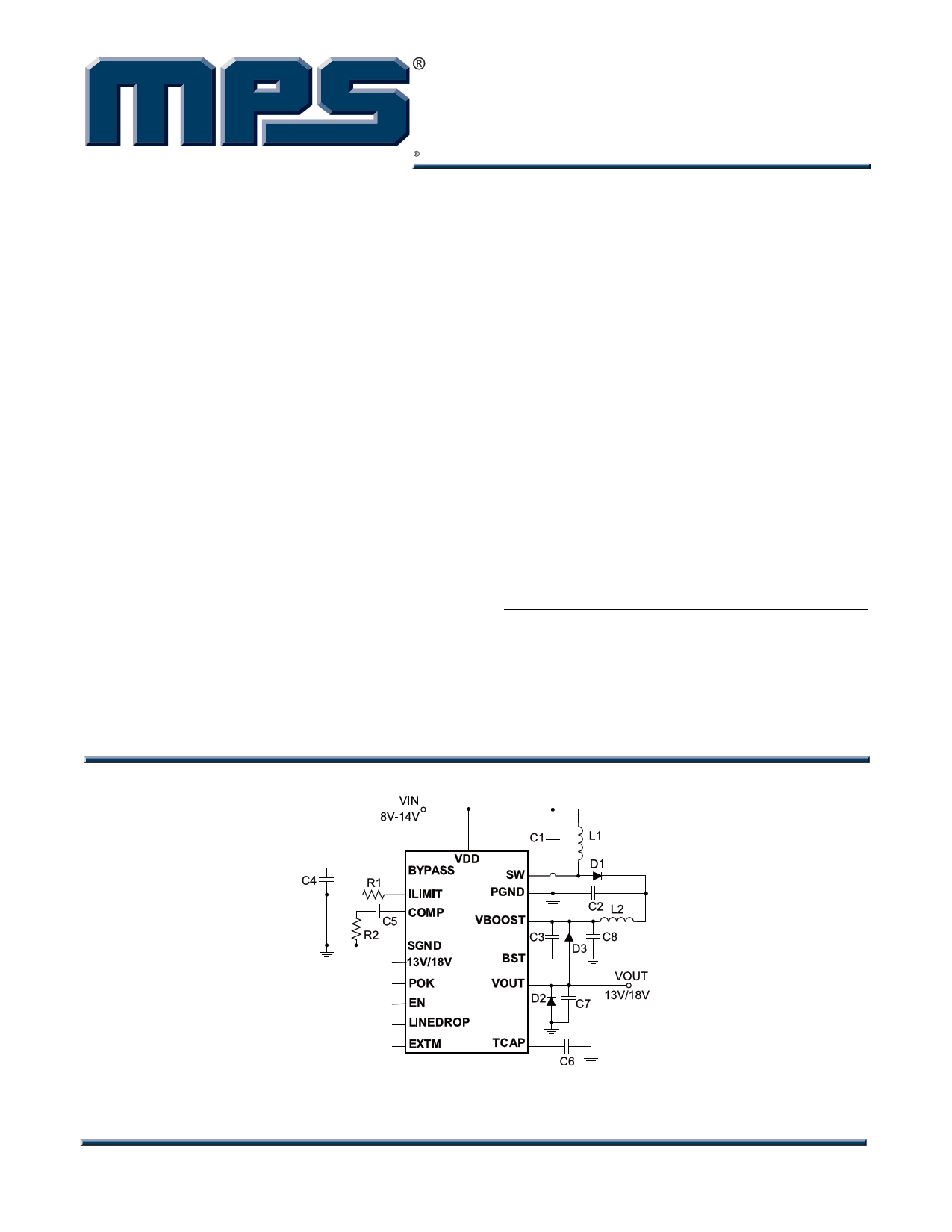
TYPICAL APPLICATION
FEATURES
• DiSEqC 1.x Compatibility
• Up to 550mA Output Current
• 8V to 14V Input Voltage
• Boost Converter with Internal Switch
• Low Noise LDO Output
• Built-in 22kHz Tone Signal Generator
• Programmable Current Limit
• 1V Line Drop Compensation
• Adjustable Soft-start Time
• POK Indicator
• Short Circuit Protection
• Over Temperature Protection
• TSSOP16 Exposed Pad and 24-pin QFN (4
x 4mm) Packages
APPLICATIONS
• LNB Power Supply and Control for Satellite
Set Top Boxes
For MPS green status, please visit MPS website under Quality Assurance.
“MPS” and “The Future of Analog IC Technology” are Registered Trademarks of
Monolithic Power Systems, Inc.
MP8125 Rev. 1.1
10/11/2011
www.MonolithicPower.com
MPS Proprietary Information. Patent Protected. Unauthorized Photocopy and Duplication Prohibited.
© 2011 MPS. All Rights Reserved.
1
Free Datasheet http://www.datasheet4u.net/
1 page 
MP8125 – LNB POWER SUPPLY AND CONTROL VOLTAGE REGULATOR
PIN FUNCTIONS
Pin #
TSSOP-16
1
2
3
4
Pin #
QFN24
22
23, 24
2
4
55
66
77
88
9 10
10 11
11 12
12 13, 14
13 15, 16
14 17
15 19
16 20, 21
1, 3, 9, 18
Name Description
SGND
BYPASS
VDD
COMP
EN
LINEDROP
POK
13V/18V
EXTM
TCAP
ILIMIT
VOUT
VBOOST
BST
SW
PGND
NC
Analog ground.
Connect a bypass capacitor for the internal regulator.
Input supply pin.
Compensation pin for Boost regulator (47nF & 19.6kΩ is suggested).
Regulator On/Off Control Input. When this pin is low, the output is
disabled. A high level at EN turns on the converter. Connect EN to the
input source (through a 100kΩ pull-up resistor if VIN > 6V) for
automatic startup. EN cannot be left floating.
This pin provides selectable VOUT compensation for voltage drop on the
long coaxial cable. When the LINEDROP is high, the LDO output is 1V
increased. LINEDROP cannot be left floating.
Power OK. A high output indicates that LDO output is within ±12% of
nominal value. A low output means that LDO output is outside this
window.
Select 13V or 18V for output voltage. High level for 18V while low level
for 13V. This pin cannot be left floating.
External modulation input for 22kHz signaling. A high level at EXTM
turns on 22kHz signal and a low level disables it. EXTM cannot be left
floating.
Soft-start capacitor for setting rise time of the output voltage.
The ILIMIT is used to set the value of the output current limit of LDO. A
resistor from ILIMIT to GND programs the limit.
Output voltage.
Input of the internal LDO.
Supply for the internal LDO driver.
SW is the drain of the internal MOSFET switch of Boost stage.
Connect the power inductor and output rectifier to SW.
Power ground.
Not Connect.
MP8125 Rev. 1.1
10/11/2011
www.MonolithicPower.com
MPS Proprietary Information. Patent Protected. Unauthorized Photocopy and Duplication Prohibited.
© 2011 MPS. All Rights Reserved.
5
Free Datasheet http://www.datasheet4u.net/
5 Page 
MP8125 – LNB POWER SUPPLY AND CONTROL VOLTAGE REGULATOR
Figure 3—Detailed Application Schematic
MP8125 Rev. 1.1
10/11/2011
www.MonolithicPower.com
MPS Proprietary Information. Patent Protected. Unauthorized Photocopy and Duplication Prohibited.
© 2011 MPS. All Rights Reserved.
11
Free Datasheet http://www.datasheet4u.net/
11 Page | ||
| Páginas | Total 13 Páginas | |
| PDF Descargar | [ Datasheet MP8125.PDF ] | |
Hoja de datos destacado
| Número de pieza | Descripción | Fabricantes |
| MP8125 | LNB Power Supply and Control Voltage Regulator | MPS |
| MP8126 | Cooling Fan Motor | Gate |
| MP8126 | LNB-Power Supply and Control-Voltage Regulator | MPS |
| MP8126DF | LNB-Power Supply and Control-Voltage Regulator | MPS |
| Número de pieza | Descripción | Fabricantes |
| SLA6805M | High Voltage 3 phase Motor Driver IC. |
Sanken |
| SDC1742 | 12- and 14-Bit Hybrid Synchro / Resolver-to-Digital Converters. |
Analog Devices |
|
DataSheet.es es una pagina web que funciona como un repositorio de manuales o hoja de datos de muchos de los productos más populares, |
| DataSheet.es | 2020 | Privacy Policy | Contacto | Buscar |