|
|
|
PDF WPCT210 Data sheet ( Hoja de datos )
| Número de pieza | WPCT210 | |
| Descripción | Trusted Platform Module | |
| Fabricantes | Nuvoton | |
| Logotipo | ||
Hay una vista previa y un enlace de descarga de WPCT210 (archivo pdf) en la parte inferior de esta página. Total 25 Páginas | ||
|
No Preview Available !
December 2009
Revision 2.0
WPCT210 Trusted Platform Module (TPM) Version 1.2
General Description
The Nuvoton WPCT210, a single-chip Trusted Platform
Module (TPM), is a third generation Nuvoton SafeKeeper
device that implements the Trusted Computing Group
(TCG) version 1.2 specification for PC-Client TPM.
The WPCT210 is designed to reduce system boot time and
Trusted OS loading time. It provides a complete solution for PC
security for a wide range of PC applications. The WPCT210 is
Microsoft Windows Vista and Windows 7 compliant.
Features
General
■ Complete, single-chip TPM solution
— No external parts required
■ Compatible with TPM 1.2 Main (Rev 103) and PC Client
Specifications
■ Host Interface
— TPM 1.2 standard interface (TIS) with five localities
— Supports legacy locality by using TIS protocol with
I/O mapped registers
■ Secure General-Purpose I/O (GPIO)
— Five GPIO pins
— I/O pins individually configured as input or output
— Configurable internal pull-up resistors
— TCG 1.2-defined interface
— Dedicated Physical Presence (PP) pin with config-
urable pull-up or pull-down resistor
■ Tick Counter
Bus Interface
■ LPC Bus Interface
— Based on Intel’s LPC Interface Specification Revi-
sion 1.1, August 2002
— TPM 1.2 Interface (TIS)
Clocking and Supply
■ On-Chip Clock Generator
■ Power Supply
— 3.3V supply operation
— Separate pins for main (VDD) and standby (VSB)
power supplies
— Low standby power consumption
Software
■ TPM BIOS drivers: Memory Absent (MA) and Memory
Present (MP)
■ TPM Device Driver for Microsoft Windows 2000 and
Windows XP. Microsoft Windows Vista and Windows 7
include a built-in TPM driver.
■ NTRU Cryptosystems Core TCG Software Stack
(CTSS)
■ Wave Systems Cryptographic Service Provider (CSP)
with either EMBASSY® Security Center (ESC) or EM-
BASSY® Trust Suite (ETS)
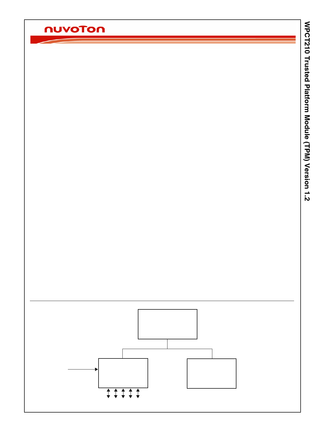
System Block Diagram
South Bridge
Physical
Presence
WPCT210
LPC Bus
SuperI/O
© 2009 Nuvoton Technology Corporation
GPIO
www.nuvoton.com
1 page 
Table of Contents (Continued)
5.2.6 Output, PCI 3.3V Compatible ...................................................................................... 16
5.2.7 Notes and Exceptions .................................................................................................. 17
5.3 INTERNAL RESISTORS ........................................................................................................... 18
5.3.1 Pull-Up Resistor ........................................................................................................... 19
5.3.2 Pull-Down Resistor ...................................................................................................... 19
5.4 AC ELECTRICAL CHARACTERISTICS .................................................................................... 20
5.4.1 AC Test Conditions ................................................................................................... 20
5.4.2 Reset Timing ............................................................................................................... 21
VSB Power-Up Reset ............................................................................................. 21
VDD Power-Up Reset .......................................................................................... 21
5.4.3 LPC Interface Timing ................................................................................................... 22
LCLK and LRESET ............................................................................................... 22
LPC Signals ............................................................................................................ 23
5.5 PACKAGE THERMAL INFORMATION ..................................................................................... 24
Physical Dimensions......................................................................................................................................... 25
Revision 2.0
5 www.nuvoton.com
5 Page 
3.0 I/O Configuration Registers (Continued)
3.1.3 Reset Configuration Setup
The default configuration setup of the WPCT210 is:
— The configuration base address is according to Table 3 on page 10.
— TPM logical device is disabled.
— The TPM interface is in Legacy mode.
— All host configuration registers are set to their default values unless explicitly stated otherwise.
3.1.4 Register Type Abbreviations
The following abbreviations are used to indicate the Register Type:
● R/W= Read/Write.
● RO= Read-only.
Write 0 to reserved bits unless another “required value” is specified. This method can be used for registers containing bits
of all types.
Revision 2.0
11 www.nuvoton.com
11 Page | ||
| Páginas | Total 25 Páginas | |
| PDF Descargar | [ Datasheet WPCT210.PDF ] | |
Hoja de datos destacado
| Número de pieza | Descripción | Fabricantes |
| WPCT210 | Trusted Platform Module | Nuvoton |
| Número de pieza | Descripción | Fabricantes |
| SLA6805M | High Voltage 3 phase Motor Driver IC. |
Sanken |
| SDC1742 | 12- and 14-Bit Hybrid Synchro / Resolver-to-Digital Converters. |
Analog Devices |
|
DataSheet.es es una pagina web que funciona como un repositorio de manuales o hoja de datos de muchos de los productos más populares, |
| DataSheet.es | 2020 | Privacy Policy | Contacto | Buscar |