|
|
|
PDF RX-E100RSB Data sheet ( Hoja de datos )
| Número de pieza | RX-E100RSB | |
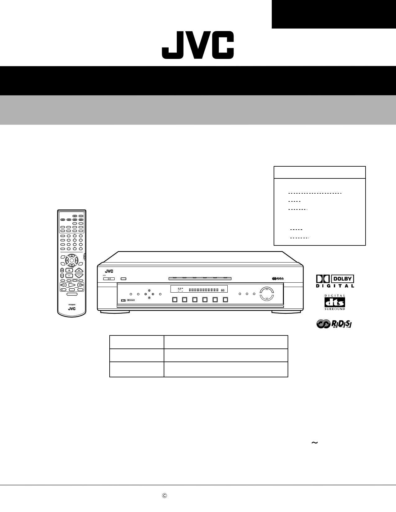
| Descripción | AUDIO/VIDEO CONTROL RECEIVER SERVICE MANUAL | |
| Fabricantes | JVC | |
| Logotipo | ||
Hay una vista previa y un enlace de descarga de RX-E100RSB (archivo pdf) en la parte inferior de esta página. Total 52 Páginas | ||
|
No Preview Available !
RX-E100RSL/RX-E100RSB
SERVICE MANUAL
AUDIO/VIDEO CONTROL RECEIVER
AUDIO
DVD STB VCR
TV
SLEEP TV DIRECT
DVD STB VCR
TV
ANALOG/DIGITAL
INPUT
TAPE
FM
AM
SOUND
BASS+
1
CENTER
23
TEST
BASS–
4
REAR-L
56
BASS BOOST TREBLE+
7
REAR-R
89
EFFECT
TREBLE–
10
RETURN
SUBWOOFER
0 +10
FM MODE
100+
DISPLAY MODE
EON SELECT
DVD MENU
PTY(
DSP
MODE
EON
ENTER
RDS
DVD
MENU
PTY9
SURROUND
ON/OFF
PTY SEARCH
TV VOL CHANNEL
VOLUME
TV/VIDEO
DIMMER
VCR MUTING
CONTROL
/REW
DOWN
REC
PLAY
TUNING
STOP
FF/
UP
PAUSE
RM-SRXE100R REMOTE CONTROL
HOME CINEMA CONTROL CENTER
RX-E100RSL
RX-E100RSB
Area Suffix
RX-E100RSL
B U.K.
E Continental Europe
EN Northern Europe
RX-E100RSB
E Continental Europe
EN Northern Europe
STANDBY
TV DILECT
SETTING ADJUST
CONTROL
MEMORY
DIGITAL
SURROUND D I G I T A L
RX-E100R HOME CINEMA CONTROL CENTER
DVD
STB
VCR
TV
TAPE
FM/AM
ANALOG L C R PRO LOGIC SLEEP
LPCM SUBWFR LFE DSP
DOLBY D
DGTL AUTO
DTS LS S RS INPUT ATT
TUNED ST AUTO MUTING
MHZ
KHZ
VOL
DVD
STB
VCR
TV
TAPE
FM/AM
INPUT SURROUND
ANALOG/DIGITAL ON/OFF
DSP
MODE
INPUT ATT
MASTER VOLUME
Each difference points
MODEL
Source indication lens colour
RX-E100RSL
SILVER
RX-E100RSB
SILVER BLACK
Contents
Safety precautions --------------------------------------------------------1- 2
Disassembly method -----------------------------------------------------1- 3
Adjustment method -------------------------------------------------------1- 8
Description of major ICs -------------------------------------------------1- 9
15
COPYRIGHT 2001 VICTOR COMPANY OF JAPAN, LTD.
No.20951
May 2001
1 page 
RX-E100RSL/RX-E100RSB
Removing the audio board (See Fig.8)
Prior to performing the following procedure, remove
the top cover , the rear panel and the each board.
1. Disconnect the card wire from connector CN411 on
the audio board.
2. Disconnect the harness from connector CN205 on the
audio board.
3. Disconnect the harness from connector CN515,
CN516, and CN517on the main board.
4. Remove the harness band fixing the harness.
5. Remove the three screws G attaching the audio
board assembly.
Removing the main board (See Fig.9)
Prior to performing the following procedure, remove
the top cover, the rear panel and audio board.
1. Remove the harness band fixing the harness.
2. Disconnect the harness from connector CN707 on
the power supply board .
3. Disconnect the harness from connector CN202 and
CN206 on the main board .
4. Remove the five screws H and the two screws I
attaching the main board.
Main board
CN515
CN517 CN516
CN411
power
supply
board
G
Audio
board
H
I
H
Main
board
H
Power
transformer
Harness
band
Fig.8
CN205
Power / Fuse
board
H
I
CN707
CN206
CN202
Harness
band
Fig.9
J
Removing the Heat sink
(See Fig.10 to 11)
1. Remove the ten screws K and four screws L
attaching the heat sink.
Main board
rear side
2. Remove the two screws J attaching the heat sink
from the rear side of main board.
Heat sink
L
K
Fig.10
KK
J
L
Fig.11
1-5
5 Page 
UPD784215AGC103 (IC671) : UNIT CPU
1.Pin layout
75 ~ 51
76 50
RX-E100RSL/RX-E100RSB
100 26
1 ~ 25
2.Pin function
Pin No.
Symbol
1~8
9
10
11
12
13
14
15
16
17
18
19
20
21
22
23
24
25~32
33
34,35
36
37,38
39
40
41
42
43
44
45,46
47
48
49
50
51,52
53
54~63
64,65
66
67
68
69,70
71
72
73~80
81
82
83
84
85
86
87
88
89
90~93
94
95~100
VDD
X2
X1
VSS
XT2
XT1
RESET
AUTODATA
LOCK
DIGITAL0
FORMAT
CHANNEL
ERR
RSTDET
AVDD
AVREF0
AVSS
AV REF1
RX,TX
DSPCOM
DSPSTS
DSPCLK
DSPRDY
MIDIO_IN/OUT
MICK
MICS
MILP
MIACK
DSPRST
CDTI/CDTO
CCLK
CS
XTS
PD
GND
VDD
3D-ON
3D-ON
ANA/T-TONE
REF-MIX
D.MUTE
S.MUTE
ASW1~4
TEST
I/O
-
-
O
I
-
O
I
I
I
I
I
I
I
I
I
-
-
-
-
-
-
-
-
I
O
I
I
-
I/O
O
O
O
O
-
O
-
I/O
O
O
O
-
O
-
-
-
-
O
O
O
-
O
O
-
O
-
-
Function
Non connect
Power supply terminal
Connecting the crystal oscillator for system main clock
Connecting the crystal oscillator for system main clock
Connect to GND
Connecting the crystal oscillator for system sub clock
Connecting the crystal oscillator for system sub clock
System reset signal input
Output of DSP to general-purpose port
Output of DSP to general-purpose port
Output of DSP to general-purpose port
Output of DSP to general-purpose port
Output of DSP to general-purpose port
Output of DSP to general-purpose port
Reset signal input
Power supply terminal
Connect to GND
Connect to GND
Connect to GND
Non connect
Power supply terminal
Not use
Non connect
Communication port from IC701
Status communication port to IC701
Clock input from IC701
Ready signal input from IC701
Non connect
Interface I/O terminal with microcomputer
Interface I/O terminal with microcomputer of clock signal
Interface I/O terminal with microcomputer of chip select
Interface I/O termonal with microcomputer
Interface I/O termonal with microcomputer
Non connect
Reset signal output of DSP
Non connect
Interface I/O terminal with microcomputer
Interface I/O terminal with microcomputer of clock signal
Interface I/O terminal with microcomputer of chip select
OSC Select
Non connect
Reset signal output
Connect to GND
Non connect
Power supply
Non connect
Switch at output destination of surround channel
Test tone control
Control at output destination of LFE channel
Non connect
Mute of the digital out terminal is controlled
Mute of the audio signal is controlled
Non connect
Selection of digital input selector
Test terminal
Non connect
1-11
11 Page | ||
| Páginas | Total 52 Páginas | |
| PDF Descargar | [ Datasheet RX-E100RSB.PDF ] | |
Hoja de datos destacado
| Número de pieza | Descripción | Fabricantes |
| RX-E100RSB | AUDIO/VIDEO CONTROL RECEIVER SERVICE MANUAL | JVC |
| RX-E100RSL | AUDIO/VIDEO CONTROL RECEIVER SERVICE MANUAL | JVC |
| Número de pieza | Descripción | Fabricantes |
| SLA6805M | High Voltage 3 phase Motor Driver IC. |
Sanken |
| SDC1742 | 12- and 14-Bit Hybrid Synchro / Resolver-to-Digital Converters. |
Analog Devices |
|
DataSheet.es es una pagina web que funciona como un repositorio de manuales o hoja de datos de muchos de los productos más populares, |
| DataSheet.es | 2020 | Privacy Policy | Contacto | Buscar |