|
|
|
PDF AT42QTAN0040 Data sheet ( Hoja de datos )
| Número de pieza | AT42QTAN0040 | |
| Descripción | Driving the AT42QT2160 QMatrix Sensor IC | |
| Fabricantes | ATMEL Corporation | |
| Logotipo | ||
Hay una vista previa y un enlace de descarga de AT42QTAN0040 (archivo pdf) en la parte inferior de esta página. Total 14 Páginas | ||
|
No Preview Available !
Driving the AT42QT2160 QMatrix Sensor IC
1. Introduction
This application note shows how the AT42QT2160-MMU (QT2160) 16-key QMatrix™
Sensor IC can be connected to a microprocessor to provide touch input functionality.
Example code is provided to demonstrate how easily the QT2160 can be incorporated
into a design. The code can be run “as is” or used as a starting point for QT2160-
based projects. The example compiles to under 1 Kbyte of code including all
necessary I2C-compatible driver functions.
The example code is written in the C programming language and can easily be
adapted for many processor types. See Section 6 on page 8 for a listing of the
complete program.
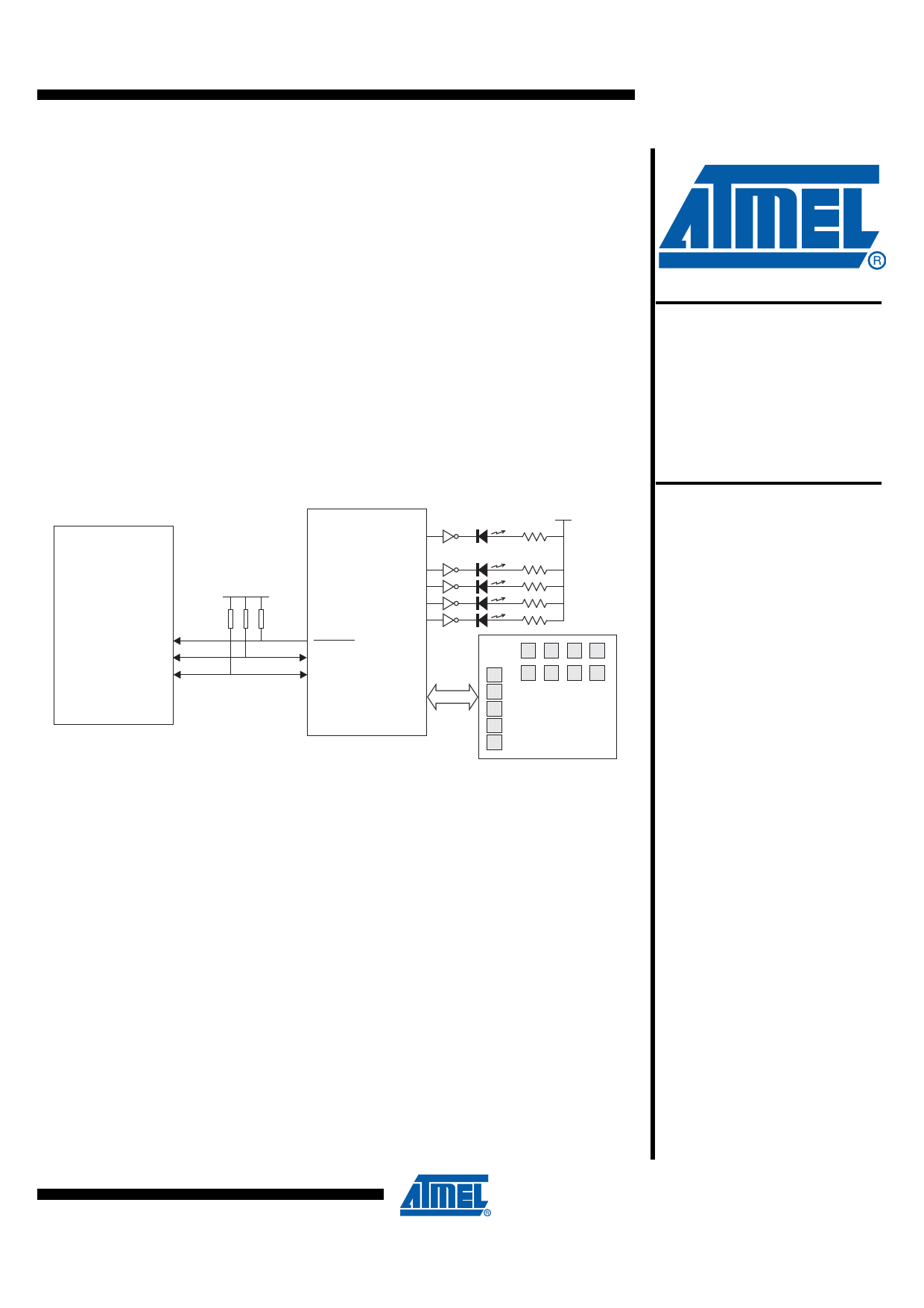
Figure 1-1. Circuit Configuration for the Example Project
P0.3
P0.7
P0.6
Host MCU
Vdd
CHANGE
SCL
SDA
GPIO3
GPO3
GPO2
GPO1
GPO0
QT2160
Vdd
8 Discrete Keys
(keys 8 – 15)
5-Key Slider
(keys 0 – 4)
QMatrix Key
Array
Driving the
AT42QT2160
QMatrix Sensor
IC
Application Note
AT42QTAN0040
2. Overview of the QT2160
2.1 Introduction
The QT2160 is designed for use with up to 16 keys and a slider (constructed from 2
keys up to 8 keys). There are three dedicated general-purpose input/outputs (GPIO),
which can be used as inputs (for example, for mechanical switches) or as driven
outputs. There are eight shared general-purpose outputs (GPO). Pulse switch
modulation (PWM) control can be applied to all GPIO and GPO pins.
Keys are configured in a matrix format that minimizes the number of required scan
lines and device pins. The key electrodes can be designed into a conventional printed
circuit board (PCB) or flexible printed circuit board (FPCB) as a copper pattern, or as
printed conductive ink on plastic film. The QT2160 can be fine tuned to optimize
operation with the electrode design.
Full details of the QT2160 can be found in the QT2160 datasheet, which should be
read in conjunction with this application note.
10702A–AT42–07/08
1 page 
Driving the AT42QT2160
5. I2C-compatible Driver
5.1 I2C-compatible Communication
I2C-compatible communication is a major aspect of any program involving the QT2160. Some
form of I2C-compatible driver must be written to handle read and write operations to the device.
Most current microprocessors include a hardware I2C-compatible master function, which could
be programmed to efficiently handle these transfers, but the driver code will always be specific to
the hardware. The example code in this application note includes a software-based
I2C-compatible driver using two port pins of the host microcontroller. It could easily be ported to
many processor types.
The I2C-compatible communication sequences used to read and write data to the QT2160 are
fully described in the QT2160 datasheet.
5.2 Design Approach
The driver presented here uses bit-banging techniques to manage the I2C-compatible interface.
The driver is structured in three layers:
• In the bottom layer, code-macros are used to drive the SCL and SDA pins and to create
START and STOP conditions on the I2C-compatible bus.
• In the middle layer, the SendByte() and GetByte() functions sequence the transmission and
reception of bytes including handling the ACK bit.
• In the top layer, the WriteQtI2c() and ReadQtI2c() functions can be called by an application to
transfer one or more bytes to and from the QT2160. Note that for the sake of clarity, the driver
is simplified (for example, it includes no timeouts).
The following sections describe the driver and should be read in conjunction with the code
listing.
5.3 Macros
Table 5-1 describes the various code macros used to drive the SCL and SDA pins. Any macro
that changes the state of a pin includes a fixed 5 µs delay following the edge. The 5 µs delay
ensures the 100 kHz I2C-compatible specification is met and results in a bus clock rate of around
66 kHz.
Table 5-1. Code Macros for the I2C-compatible Bus Functions
Macro
I2cDelay
Description
Generates a program-delay to guarantee I2C-compatible timing
requirements. The constant BUS_DELAY should be adjusted to
produce a 5 µs delay.
SetHiSCL
Floats the SCL pin. SCL is then pulled high by the pull-up resistor.
Note: the QT2160 may extend the low clock-phase. This means that
after floating the pin, the driver waits until the high state is achieved
before continuing.
SetLoSCL
Drives the SCL pin low. There is no need to wait for the pin to achieve
the low state.
SetHiSDA
Floats the SDA pin. SDA is then pulled high by the pull-up resistor.
After floating the pin, the driver waits until the high state is achieved
before continuing.
10702A–AT42–07/08
5
5 Page 
Driving the AT42QT2160
/*=====================================================================================
Function:
SendByte()
Input:
Byte to send
Output:
I2C_OK if device ACKs, I2C_FAIL if device NACKs
====================================================================================*/
uint8_t SendByte ( uint8_t TxByte )
{
uint8_t i,b, Result = I2C_OK;
for (b = 0; b < 8; b++)
{
if ( TxByte & 0x80 )
SetHiSDA
else
SetLoSDA
SendCLOCK
TxByte <<= 1; /* shift out data byte */
}
FloatSDA /* prepare to receive ACK bit */
SetHiSCL /* read ACK bit */
if ( SDA == 1 )
Result = I2C_FAIL;
SetLoSCL
return Result;
}
/*=====================================================================================
Function:
GetByte()
Input:
State of ACK bit to send
Output:
Received byte
====================================================================================*/
uint8_t GetByte ( uint8_t AckBit )
{
uint8_t i,b, RxByte = 0;
FloatSDA
for (b = 0; b < 8; b++)
{
RxByte <<= 1; /* shift in data byte */
SetHiSCL;
10702A–AT42–07/08
11
11 Page | ||
| Páginas | Total 14 Páginas | |
| PDF Descargar | [ Datasheet AT42QTAN0040.PDF ] | |
Hoja de datos destacado
| Número de pieza | Descripción | Fabricantes |
| AT42QTAN0040 | Driving the AT42QT2160 QMatrix Sensor IC | ATMEL Corporation |
| Número de pieza | Descripción | Fabricantes |
| SLA6805M | High Voltage 3 phase Motor Driver IC. |
Sanken |
| SDC1742 | 12- and 14-Bit Hybrid Synchro / Resolver-to-Digital Converters. |
Analog Devices |
|
DataSheet.es es una pagina web que funciona como un repositorio de manuales o hoja de datos de muchos de los productos más populares, |
| DataSheet.es | 2020 | Privacy Policy | Contacto | Buscar |