|
|
|
PDF IRFH5306TRPBF Data sheet ( Hoja de datos )
| Número de pieza | IRFH5306TRPBF | |
| Descripción | HEXFET Power MOSFET | |
| Fabricantes | International Rectifier | |
| Logotipo | ||
Hay una vista previa y un enlace de descarga de IRFH5306TRPBF (archivo pdf) en la parte inferior de esta página. Total 8 Páginas | ||
|
No Preview Available !
VDS
RDS(on) max
(@VGS = 10V)
Qg (typical)
RG (typical)
ID
(@Tc(Bottom) = 25°C)
30
8.1
7.8
1.4
44
Applications
• Control MOSFET for buck converters
V
mΩ
nC
Ω
A
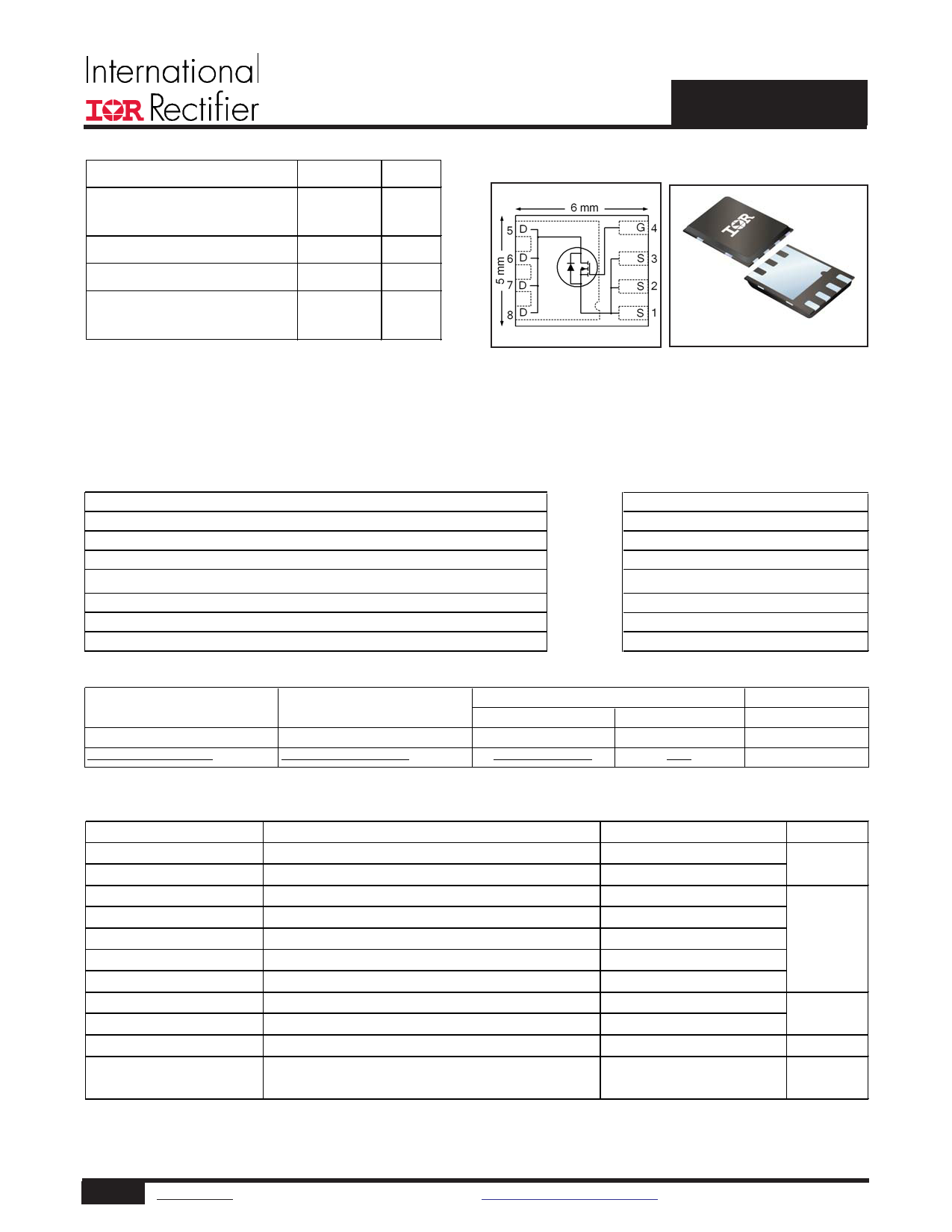
IRFH5306PbF
HEXFET® Power MOSFET
PQFN 5X6 mm
Features and Benefits
Fe a ture s
Low charge (typical 7.8nC)
Low thermal resistance to PCB (< 4.9°C/W)
100% Rg tested
Low profile (< 0.9 mm)
Industry-standard pinout
Compatible with existing Surface Mount Techniques
RoHS compliant containing no lead, no bromide and no halogen
MSL1, Industrial qualification
results in
⇒
Be ne fi ts
Lower switching losses
Increased power density
Increased reliability
Increased power density
Multi-vendor compatibility
Easier manufacturing
Environmentally friendly
Increased reliability
Orderable part number
Package Type
IRFH5306TRPBF
IRFH5306TR2PBF
PQFN 5mm x 6mm
PQFN 5mm x 6mm
Standard Pack
Form
Quantity
Tape and Reel
4000
Tape and Reel
400
Note
EOL notice #259
Absolute Maximum Ratings
Parameter
VDS
VGS
ID @ TA = 25°C
ID @ TA = 70°C
ID @ TC(Bottom) = 25°C
ID @ TC(Bottom) = 100°C
IDM
PD @TA = 25°C
PD @ TC(Bottom) = 25°C
Drain-to-Source Voltage
Gate-to-Source Voltage
Continuous Drain Current, VGS @ 10V
Continuous Drain Current, VGS @ 10V
Continuous Drain Current, VGS @ 10V
cContinuous Drain Current, VGS @ 10V
Pulsed Drain Current
gPower Dissipation
gPower Dissipation
gLinear Derating Factor
TJ Operating Junction and
TSTG
Storage Temperature Range
Max.
30
±20
15
13
44
28
60
3.6
26
0.029
-55 to + 150
Units
V
A
W
W/°C
°C
Notes through
are on page 8
1 www.irf.com © 2014 International Rectifier
Submit Datasheet Feedback
January 20, 2014
1 page 
25
ID = 15A
20
15
10
TJ = 25°C
TJ = 125°C
5
0 2 4 6 8 10 12 14 16
VGS, Gate -to -Source Voltage (V)
Fig 12. On-Resistance vs. Gate Voltage
IRFH5306PbF
200
180 ID
TOP 3.9A
160 7.7A
140 BOTTOM 15A
120
100
80
60
40
20
0
25 50 75 100 125 150
Starting TJ , Junction Temperature (°C)
Fig 13. Maximum Avalanche Energy vs. Drain Current
15V
VDS
L
RG
20V
tp
D.U.T
IAS
0.01Ω
DRIVER
+
-
VDD
A
Fig 14a. Unclamped Inductive Test Circuit
V(BR)DSS
tp
IAS
Fig 14b. Unclamped Inductive Waveforms
VDS
VGS
RG
RD
D.U.T.
V1G0SV
Pulse Width ≤ 1 µs
Duty Factor ≤ 0.1
+-VDD
Fig 15a. Switching Time Test Circuit
5 www.irf.com © 2014 International Rectifier
VDS
90%
10%
VGS
td(on) tr
td(off) tf
Fig 15b. Switching Time Waveforms
Submit Datasheet Feedback
January 20, 2014
5 Page | ||
| Páginas | Total 8 Páginas | |
| PDF Descargar | [ Datasheet IRFH5306TRPBF.PDF ] | |
Hoja de datos destacado
| Número de pieza | Descripción | Fabricantes |
| IRFH5306TRPBF | HEXFET Power MOSFET | International Rectifier |
| Número de pieza | Descripción | Fabricantes |
| SLA6805M | High Voltage 3 phase Motor Driver IC. |
Sanken |
| SDC1742 | 12- and 14-Bit Hybrid Synchro / Resolver-to-Digital Converters. |
Analog Devices |
|
DataSheet.es es una pagina web que funciona como un repositorio de manuales o hoja de datos de muchos de los productos más populares, |
| DataSheet.es | 2020 | Privacy Policy | Contacto | Buscar |