|
|
|
PDF MAX17105 Data sheet ( Hoja de datos )
| Número de pieza | MAX17105 | |
| Descripción | 8-String WLED Driver | |
| Fabricantes | Maxim Integrated | |
| Logotipo | ||
Hay una vista previa y un enlace de descarga de MAX17105 (archivo pdf) en la parte inferior de esta página. Total 26 Páginas | ||
|
No Preview Available !
19-4562; Rev 1; 12/09
EVAALVUAAILTAIOBNLEKIT
8-String WLED Driver with Integrated Step-Up
Regulator and SMBus/PWM Dimming Capability
General Description
The MAX17105 is a high-efficiency driver for white-light-
emitting diodes (WLEDs). It is designed for large liquid-
crystal displays (LCDs) that employ an array of LEDs as
the light source. An internal switch-current mode step-up
controller drives the LED array, which can be configured
for up to 8 strings in parallel and 10 LEDs per string.
Each string is terminated with ballast that achieves Q2%
current regulation accuracy, ensuring even LED bright-
ness. The MAX17105 has a wide input voltage range
from 6V to 28V, and provides adjustable 0 to 30mA full-
scale LED current.
The MAX17105 can internally generate a digitally adjusted
pulse-width modulation (DPWM) signal for accurate
WLED dimming control. The DPWM frequency is resis-
tor programmable, while DPWM duty cycle is controlled
directly from an external PWM signal or through a control
word through the MAX17105’s SMBus™ interface. This
DPWM control provides a dimming range with 8-bit reso-
lution and supports Intel display power-saving technol-
ogy (DPST) to maximize battery life. The MAX17105 also
has direct PWM control mode, in which the PWMI directly
controls the LED current turn on/off and the SMBus inter-
face is disabled.
The MAX17105 has multiple features to protect the con-
troller from fault conditions. Separate feedback loops
limit the output voltage under any circumstance, ensur-
ing safe operation. Once an open string is detected, the
string is disabled while other strings operate normally.
The MAX17105 also features short LED detection. The
shorted strings are also disabled. The controller features
cycle-by-cycle current limit to provide constant operation
and soft-start capability. If the MAX17105 is in current-
limit condition, the step-up regulator is latched off after
an internal timer expires. A thermal-shutdown circuit
provides another level of protection. When the input over-
current-limit fault, thermal shutdown, or output-voltage
short condition happens, the input p-channel MOSFET
is turned off and the step-up regulator output is isolated
from the input supply.
The MAX17105 is available in a thermally enhanced,
24-pin, 4mm x 4mm, thin QFN package with exposed pad.
Notebook, Subnotebook,
and Tablet Computer
Displays
Applications
Automotive Systems
Handy Terminals
Features
S 6V to 28V Input Supply Voltage
S Up to Eight Parallel-String Multiple Series
Connected LEDs
S 500kHz-to-2MHz Adjustable Switching Frequency
S 0.15I Internal HV Power MOSFET (45V max)
S Low-String Feedback Voltage: 500mV at 20mA
LED current
S Full-Scale LED Current Adjustable from 0mA to
30mA
S Q2% Current Regulation Accuracy Between Strings
S 100:1 Dimming Ratio at 25kHz Direct PWM
Frequency
S 100Hz to 30kHz PWMI Input Range for DPWM
Mode and 10kHz Q5% for SMBus Mode
S 100Hz to 5kHz Adjustable DPWM Frequency
S Full-Range Dimming with 8-Bit Resolution
S Open and Short LED Protection
S Output Overvoltage Protection
S Thermal Shutdown
S FAULT Output to Drive p-Channel MOSFET
S Small 24-Pin, 4mm x 4mm, Thin QFN Package
Ordering Information
PART
TEMP RANGE
PIN-PACKAGE
MAX17105 ETG+ -40NC to +85NC
24 TQFN-EP*
+Denotes a lead(Pb)-free/RoHS-compliant package.
*EP = Exposed pad.
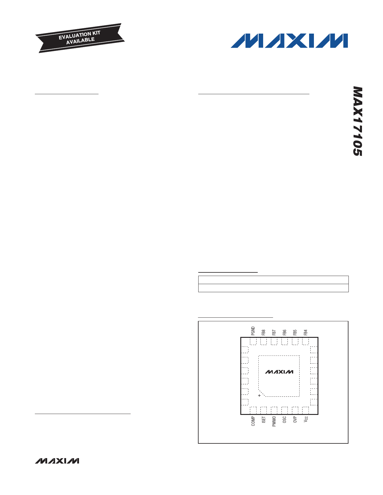
Pin Configuration
TOP VIEW
18 17 16 15 14 13
LX 19
12 FB3
PWMI 20
11 FB2
EN 21
SCL 22
MAX17105
10 FB1
9 SGND
SDA 23
8 FAULT
DFSET 24
7 IN
12 3 4 56
THIN QFN
4mm x 4mm
SMBus is a trademark of Intel Corp.
Simplified Operating Circuit appears at end of data sheet.
________________________________________________________________ Maxim Integrated Products 1
For pricing, delivery, and ordering information, please contact Maxim Direct at 1-888-629-4642,
or visit Maxim’s website at www.maxim-ic.com.
1 page 
8-String WLED Driver with Integrated Step-Up
Regulator and SMBus/PWM Dimming Capability
ELECTRICAL CHARACTERISTICS
(Circuit of Figure 1. VIN = 12V, CCOMP = 33nF, RCOMP = 1kI, RISET = 50kI, ROSC = 100kI, RDFSET = 250kI, PWMI = SGND,
CPWMO = 1µF, TA = -40NC to +85NC, unless otherwise noted. Typical values are at TA = +25NC.) (Note 2)
PARAMETER
SUPPLY
CONDITIONS
MIN TYP MAX UNITS
IN Input Voltage Range (Note 1)
VCC = open, EN = high (Note 5)
EN = SGND, SMBus
mode
All functions available
SMBus interface only
5.5 28
6.3 28
3.9 4.0
V
IN Input Voltage UVLO
Threshold (SMBus Mode Only)
(Note 2)
Rising edge, hysteresis = 150mV
Falling edge, hysteresis = 150mV
5.9
5.75
6.2
6.05
V
IN Quiescent Current
VCC Output Voltage
VCC Current Limit
VCC UVLO Threshold
STEP-UP REGULATOR
LX On-Resistance
Operating Frequency
Maximum Duty Cycle
LX Current Limit
CONTROL INPUT
Logic-Input High Level
Logic-Input Low Level
SDA Output-Low Sink Current
SDA, SCL Input Bias Current
LED CURRENT
Full-Scale FB_ Output Current
Adjustable Range (Note 3)
Full-Scale FB_ Output Current
Current Regulation Between
Strings
Minimum FB_ Regulation Voltage
FB_ On-Resistance
FB_ On-Time
MAX17105 is enabled at minimum brightness,
in SMBus mode and no load, VIN = 28V
MAX17105 is enabled in SMBus mode, and is under
IN UVLO, VIN = 5.5V
MAX17105 is disabled
MAX17105 is enabled, 6V < VIN < 28V, 0 < IVCC < 10mA
MAX17105 is disabled, VIN = 12V
VCC is forced to 4.5V
Rising edge, typical hysteresis = 85mV
100mA from LX to PGND
ROSC = 50kI
ROSC = 100kI
ROSC = 200kI
At fSW = 1MHz
Duty cycle = 75%
SDA, SCL, PWMI, EN
SDA, SCL, PWMI, EN
VSDA = 0.4V
TA = +25NC
PWM only dimming mode
SMBus-enabled dimming modes
RISET = 33.3kI
RISET = 50.0kI
RISET = 66.6kI
VISET < 0.4V
IFB_ = 30mA
IFB_ = 20mA
IFB_ = 15mA
IFB_ = 30mA
VFB_ = 50mV
4.7
3.7
15
4.00
1.7
0.9
0.45
93
2.4
2.1
4
-1
15
15
28.8
18.9
14.25
0.2
-2.5
-2.5
-2.5
400
3.0
1.1
60
5.3
4.95
70
4.45
mA
FA
V
mA
V
0.3 I
2.3
1.1 MHz
0.6
98 %
3.4 A
V
0.8 V
mA
+1 FA
30
25
31.2
21
15.75
0.4
+2.5
+2.5
+2.5
770
26
mA
mA
%
mV
I
ns
________________________________________________________________________________________ 5
5 Page 
8-String WLED Driver with Integrated Step-Up
Regulator and SMBus/PWM Dimming Capability
Pin Description
PIN NAME
FUNCTION
Step-Up Regulator Compensation Pin. Connect a 0.033FF ceramic capacitor and 1kI resistor from
1
COMP
COMP to SGND and an additional 220pF capacitor from COMP to SGND. When the MAX17105
shuts down, COMP is discharged to 0V through an internal 20kI resistor.
Full-Scale LED Current Adjustment Pin. The resistance from ISET to SGND controls the full-scale
current in each LED string:
2
ISET
ILED_MAX = 20mA O 50kI/RISET
The acceptable resistance range is 33.3kI < RISET < open, which corresponds to full-scale LED
current of 30mA > ILED_MAX > 0mA. Connecting ISET to SGND sets the test mode for 0.3mA (typ)
full-scale LED current.
Filtered PWM Signal Output. Connect a capacitor between PWMO and SGND. The capacitor forms
3 PWMO a lowpass filter with an internal 40kI (typ) resistor to filter the PWM signal into an analog signal
whose level represents the duty cycle information of the input PWM signal.
Oscillator Frequency Adjustment Pin. The resistance from OSC to SGND sets the step-up
regulator’s oscillator frequency:
4 OSC
fSW = 1MHz O 100kI/ROSC
The acceptable resistance range is 50kI < ROSC < 200kI, which corresponds to the switching
frequency of 2MHz > fSW > 500kHz.
5
OVP
Overvoltage Sense. Connect OVP to the center tap of a resistive voltage-divider from the output of
the step-up regulator to ground.
6
VCC
5V Linear-Regulator Output. VCC provides power to the MAX17105. Bypass VCC to SGND with a
ceramic capacitor of 1FF or greater.
7
IN
Power-Supply Input. VIN biases the internal 5V linear regulator that powers the device. Bypass IN
to SGND directly at the pin with a 0.1FF ceramic capacitor or greater.
External p-Channel MOSFET Gate Drive-Output. External pullup resistor is connected between
8 FAULT FAULT and IN when p-channel MOSFET is used. If the p-channel MOSFET is not used, leave
FAULT unconnected.
9
SGND
Analog Ground
10
FB1
LED String 1 Cathode Connection. FB1 is the open-drain output of an internal regulator, which
controls current through FB1. FB1 can sink up to 30mA. If unused, connect FB1 to SGND.
11
FB2
LED String 2 Cathode Connection. FB2 is the open-drain output of an internal regulator, which
controls current through FB2. FB2 can sink up to 30mA. If unused, connect FB2 to SGND.
12
FB3
LED String 3 Cathode Connection. FB3 is the open-drain output of an internal regulator, which
controls current through FB3. FB3 can sink up to 30mA. If unused, connect FB3 to SGND.
13
FB4
LED String 4 Cathode Connection. FB4 is the open-drain output of an internal regulator, which
controls current through FB4. FB4 can sink up to 30mA. If unused, connect FB4 to SGND.
14
FB5
LED String 5 Cathode Connection. FB5 is the open-drain output of an internal regulator, which
controls current through FB5. FB5 can sink up to 30mA. If unused, connect FB5 to SGND.
15
FB6
LED String 6 Cathode Connection. FB6 is the open-drain output of an internal regulator, which
controls current through FB6. FB6 can sink up to 30mA. If unused, connect FB6 to SGND.
16
FB7
LED String 7 Cathode Connection. FB7 is the open-drain output of an internal regulator, which
controls current through FB7. FB7 can sink up to 30mA. If unused, connect FB7 to SGND.
17
FB8
LED String 8 Cathode Connection. FB8 is the open-drain output of an internal regulator, which
controls current through FB8. FB8 can sink up to 30mA. If unused, connect FB8 to SGND.
_______________________________________________________________________________________ 11
11 Page | ||
| Páginas | Total 26 Páginas | |
| PDF Descargar | [ Datasheet MAX17105.PDF ] | |
Hoja de datos destacado
| Número de pieza | Descripción | Fabricantes |
| MAX1710 | High-Speed / Digitally Adjusted Step-Down Controllers for Notebook CPUs | Maxim Integrated |
| MAX17101 | Step-Down Controller | Maxim Integrated Products |
| MAX17105 | 8-String WLED Driver | Maxim Integrated |
| MAX17108 | 10-Channel High-Voltage Scan Driver and VCOM Amplifier | Maxim Integrated |
| Número de pieza | Descripción | Fabricantes |
| SLA6805M | High Voltage 3 phase Motor Driver IC. |
Sanken |
| SDC1742 | 12- and 14-Bit Hybrid Synchro / Resolver-to-Digital Converters. |
Analog Devices |
|
DataSheet.es es una pagina web que funciona como un repositorio de manuales o hoja de datos de muchos de los productos más populares, |
| DataSheet.es | 2020 | Privacy Policy | Contacto | Buscar |