|
|
|
PDF STIM300 Data sheet ( Hoja de datos )
| Número de pieza | STIM300 | |
| Descripción | Inertia Measurement Unit | |
| Fabricantes | Sensonor | |
| Logotipo | ||
Hay una vista previa y un enlace de descarga de STIM300 (archivo pdf) en la parte inferior de esta página. Total 70 Páginas | ||
|
No Preview Available !
DATASHEET
ButterflyGyro™
STIM300 Inertia Measurement Unit
1 FEATURES
o Miniature package
o Low noise
o Low bias instability
o Excellent performance in vibration and shock environments
o 6 axes offered in same package
o Electronically calibrated axis alignment
o Gyros based on Sensonor ButterflyGyroTM
o Single-crystal silicon technology
o No intrinsic wear-out effects
o High stability accelerometers and inclinometers
o Separate “AUX” input for 24 bit ADC
o Insensitive to magnetic fields
o Full EMI compliance
o Digital interface, RS422
o Fully configurable
o Continuous self-diagnostics
(38.6mm x 44.8mm x 21.5mm)
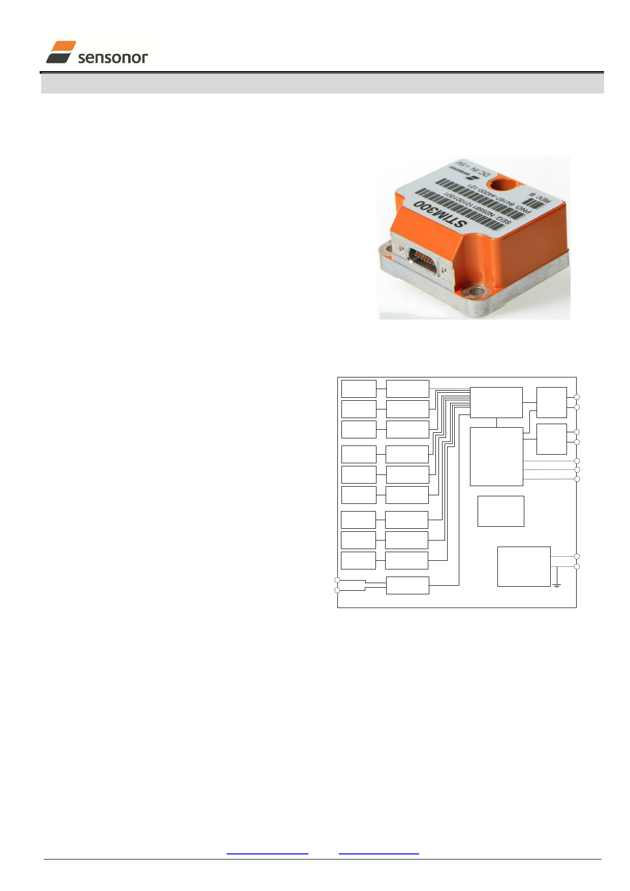
2 GENERAL DESCRIPTION
STIM300 is an IMU consisting of 3 high accuracy
MEMS-based gyros, 3 high stability accelerometers
and 3 high stability inclinometers in a miniature
package. Each axis is factory-calibrated for bias,
X-AXIS
GYRO
Y-AXIS
GYRO
GYRO DRIVE
+ ADC + LPF
GYRO DRIVE
+ ADC + LPF
CALIBRATION
AND
COMPENSATION
RS422
OUTPUT
DRIVER
TxData+
TxData-
sensitivity and compensated for temperature effects
to provide high-accuracy measurements in the
temperature range -40°C to +85°C. The unit runs off
a single +5V supply.
STIM300 communicates via a standard high-level
RS422 interface. The use of a 32-bit RISC ARM
Z-AXIS
GYRO
X-AXIS
ACC.
Y-AXIS
ACC.
Z-AXIS
ACC.
GYRO DRIVE
+ ADC + LPF
ADC + LPF
ADC + LPF
ADC + LPF
SYSTEM
CONTROLLER
RS422
INPUT
BUFFER
RxData+
RxData-
ExtTrig
TOV
Reset
microcontroller provides flexibility in the
configuration, like choice of output unit, sample rate,
low pass filter ‒3dB frequency and RS422 bit-rate
and protocol parameters. All configurable parameters
can be defined when ordering or set by customer.
When STIM300 is powered up, it will perform an
internal system check and synchronise the sensor
AUX+
AUX-
X-AXIS
INCL.
Y-AXIS
INCL.
Z-AXIS
INCL.
ADC + LPF
ADC + LPF
ADC + LPF
ADC + LPF
SELF-
DIAGNOSTICS
POWER
MANAGEMENT /
VOLTAGE AND
FREQUENCY
REFERENCES
+5V
GND
channels. As an acknowledgement of the complete
power-up sequence, it will provide special datagrams
containing part number, serial number and
configuration data. STIM300 will then automatically
Figure 2-1: STIM300 FUNCTION BLOCK DIAGRAM
proceed to provide measurement data. Connect power
and STIM300 will provide accurate measurements over the RS422 interface.
The measurement data is transmitted as packages of data on a fixed format (datagram) at intervals given by the
sample rate together with a synchronization signal (TOV). The datagram is in binary coded format in order to have an
efficient transfer of data. In addition to the measurement data itself, the datagram contains an identifier, status bytes
and a 32 bit CRC (Cyclic Redundancy Check) to provide high degree of fault detection in the transmissions. The
status bytes will flag any detected errors in the system. STIM300 can also be configured to transmit data only when
triggered by a separate digital input signal (ExtTrig).
For more advanced users, the gyro may be put in Service Mode. In this mode all the configuration parameters can be
intermediately or permanently changed by overwriting the current settings in the flash memory. In Service Mode the
commands and responses are in a human readable format (ASCII); to enable the use of terminal-type software during
typical product integration. Service Mode also provides the ability to perform single measurements, perform
diagnostics and obtain a higher detail level of detected errors reported in the status bytes.
TS1524 rev.8
Sensonor AS
Phone: +47 3303 5000 - Fax: +47 3303 5005
www.sensonor.com
1/74
April 2013
1 page 
DATASHEET
ButterflyGyro™
STIM300 Inertia Measurement Unit
TIME OF VALIDITY (TOV PIN)
Output configuration
Internal Pull-Up Resistor to Vsup
Open drain
10
kΩ
Sink capability
TOV active level
50
Active “low”
mA
Minimum time of TOV, ttov_min
Delay from internal time-tick to
TOV active, ttov_dl
Delay from TOV active (to start of
transmission, ttx_dl
50
0.5
µs
6 µs
80 µs
10
10
10
CHASSIS
Isolation resistance chassis to
500V
100
MΩ
GND (pin 15)
Note 1: Time from Power-On to start of datagram transmissions (starting with part-number datagram)
Note 2: Time from Reset release to start of datagram transmissions (starting with part-number datagram)
Note 3: Time from Power-On or Reset to the reset of the Start-Up bit (Bit 6 in the STATUS byte ref. Table 6-16).
During this period the output data should be regarded as non-valid.
Note 4: If a user-defined bit-rate larger than 1.5Mbit/s is used, the deviation may exceed the specification due to the
resolution of the bit-rate generator, ref. section 10.5.1
Note 5: Other values can be configured, ref. Table 6-8
Note 6: If time between triggers is longer, the latency will over-run. The sample counter will over-run after 127ms.
Note 7: If time between triggers is longer, the accuracy of average rate may also be reduced. Similar for accelerometer
and inclinometer outputs
Note 8: If time between triggers is longer, the integrated angle may have wrapped several times and hence the change
in angle from last sample will not be possible to calculate. Similar for accelerometer and inclinometer outputs
Note 9: For definition, ref. Figure 8-3
Note 10: For definition, ref. Figure 8-4 and Figure 8-5
Table 6-3: Functional specifications, gyros
Parameter
Conditions
Min Nom Max Unit
Note
GYRO
Full Scale (FS)
±400
°/s 1
Resolution
24 bits
0.22
°/h
Scale Factor Accuracy
±500
ppm
Non-Linearity
±200°/s
25 ppm 2
±400°/s
50 ppm 2
Bandwidth (-3dB)
262 Hz 3
Sample Rate
2000 samples/s 4
Group Delay
LP-filter -3dB = 262Hz
1.5 ms 5
LP-filter -3dB = 131Hz
3.0 ms 5
LP-filter -3dB = 66Hz
6.0 ms 5
LP-filter -3dB = 33Hz
12 ms 5
LP-filter -3dB = 16Hz
24 ms 5
Bias Range
-250 0 +250 °/h
Bias error over temperature
Static temperatures
Bias error over temperature gradients ΔT < ±1°C/min
5 °/h 6
10 °/h 7
Bias Instability
Angular Random Walk
Allan Variance @25°C
Allan Variance @25°C
0.5 °/h
0.15 °/√hr
Linear Acceleration Effect
Vibration Rectification Coefficient
Misalignment
15 °/h /g
8
0.1 °/h /g2rms
1
mrad
9
Note 1: Output is monotonous and will saturate at ±480°/s
Note 2: Largest deviation from BSL (Best Straight Line) over the range specified
Note 3: Low-pass filter -3dB frequency can be configured, ref. Table 6-8 and section 6.1.1.4
Note 4: Other values can be configured, ref. Table 6-8. Sample rate will be same for gyros, accelerometers,
inclinometers, AUX and temperature
Note 5: Total delay to start of datagram transmission = group delay + 0.5ms + ttov dl + ttx_dl. For output units with
delayed output, the group delay will be 5ms longer, ref. section 8.5.2.2.1.
Note 6: rms-value calculated on the residuals at static temperatures over the temperature range
TS1524 rev.8
5/74 April 2013
5 Page 
DATASHEET
ButterflyGyro™
STIM300 Inertia Measurement Unit
6.1.1.4 Frequency characteristics of gyros
STIM202 response, DSP-RATE-SEL-IN = 5
10
Magnitude
0.9
Phase
-1
0.8 -2
0.7 -3
0.6 -4
0.5 -5
0.4 -6
0.3 -7
0.2 -8
10
0
-10
-20
-30
-40
-50
-60
0.1 -9 -70
0 -10
0 10 20 30 40 50 60
Frequency (Hz)
-80
0
10
12
10 10
Frequency (Hz)
3
10
Figure 6-7: Frequency characteristics of gyros with low-pass filter -3dB frequency set to 16Hz
STIM202 response, DSP-RATE-SEL-IN = 4
10
Magnitude
0.9
Phase
-1
0.8 -2
0.7 -3
0.6 -4
0.5 -5
0.4 -6
0.3 -7
10
0
-10
-20
-30
-40
-50
0.2 -8 -60
0.1 -9 -70
0 -10
0 20 40 60 80 100 120
Frequency (Hz)
-80
100
101 102
Frequency (Hz)
103
Figure 6-8: Frequency characteristics of gyros with low-pass filter -3dB frequency set to 33Hz
STIM202 response, DSP-RATE-SEL-IN = 3
10
Magnitude
0.9
Phase
-1
0.8 -2
0.7 -3
0.6 -4
0.5 -5
0.4 -6
0.3 -7
0.2 -8
0.1 -9
10
0
-10
-20
-30
-40
-50
-60
-70
0 -10
0 50 100 150 200 250
Frequency (Hz)
-80
0
10
12
10 10
Frequency (Hz)
3
10
Figure 6-9: Frequency characteristics of gyros with low-pass filter -3dB frequency set to 66Hz
4
10
104
4
10
TS1524 rev.8
11/74
April 2013
11 Page | ||
| Páginas | Total 70 Páginas | |
| PDF Descargar | [ Datasheet STIM300.PDF ] | |
Hoja de datos destacado
| Número de pieza | Descripción | Fabricantes |
| STIM300 | Inertia Measurement Unit | Sensonor |
| Número de pieza | Descripción | Fabricantes |
| SLA6805M | High Voltage 3 phase Motor Driver IC. |
Sanken |
| SDC1742 | 12- and 14-Bit Hybrid Synchro / Resolver-to-Digital Converters. |
Analog Devices |
|
DataSheet.es es una pagina web que funciona como un repositorio de manuales o hoja de datos de muchos de los productos más populares, |
| DataSheet.es | 2020 | Privacy Policy | Contacto | Buscar |