|
|
|
PDF ATF-541M4 Data sheet ( Hoja de datos )
| Número de pieza | ATF-541M4 | |
| Descripción | Low Noise Enhancement Mode Pseudomorphic HEMT | |
| Fabricantes | Agilent | |
| Logotipo | ||
Hay una vista previa y un enlace de descarga de ATF-541M4 (archivo pdf) en la parte inferior de esta página. Total 16 Páginas | ||
|
No Preview Available !
Agilent ATF-541M4 Low Noise
Enhancement Mode
Pseudomorphic HEMT in a
Miniature Leadless Package
Data Sheet
Description
Agilent Technologies’s
ATF-541M4 is a high linearity,
low noise, single supply
E-PHEMT housed in a miniature
leadless package.
The ATF-541M4’s small size and
low profile makes it ideal for the
design of hybrid module and
other space-constraint devices.
The device can be used in appli-
cations such as TMA and front
end LNA for Cellular/PCS and
WCDMA base stations, LNA and
driver amplifiers for Wireless
Data and 802.11b WLAN.
In addition, the device’s superior
RF performance at higher
frequency makes it an ideal
candidate for high frequency
applications such as WLL,
802.11a WLAN, 5–6 GHz UNII
and HIPERLAN applications.
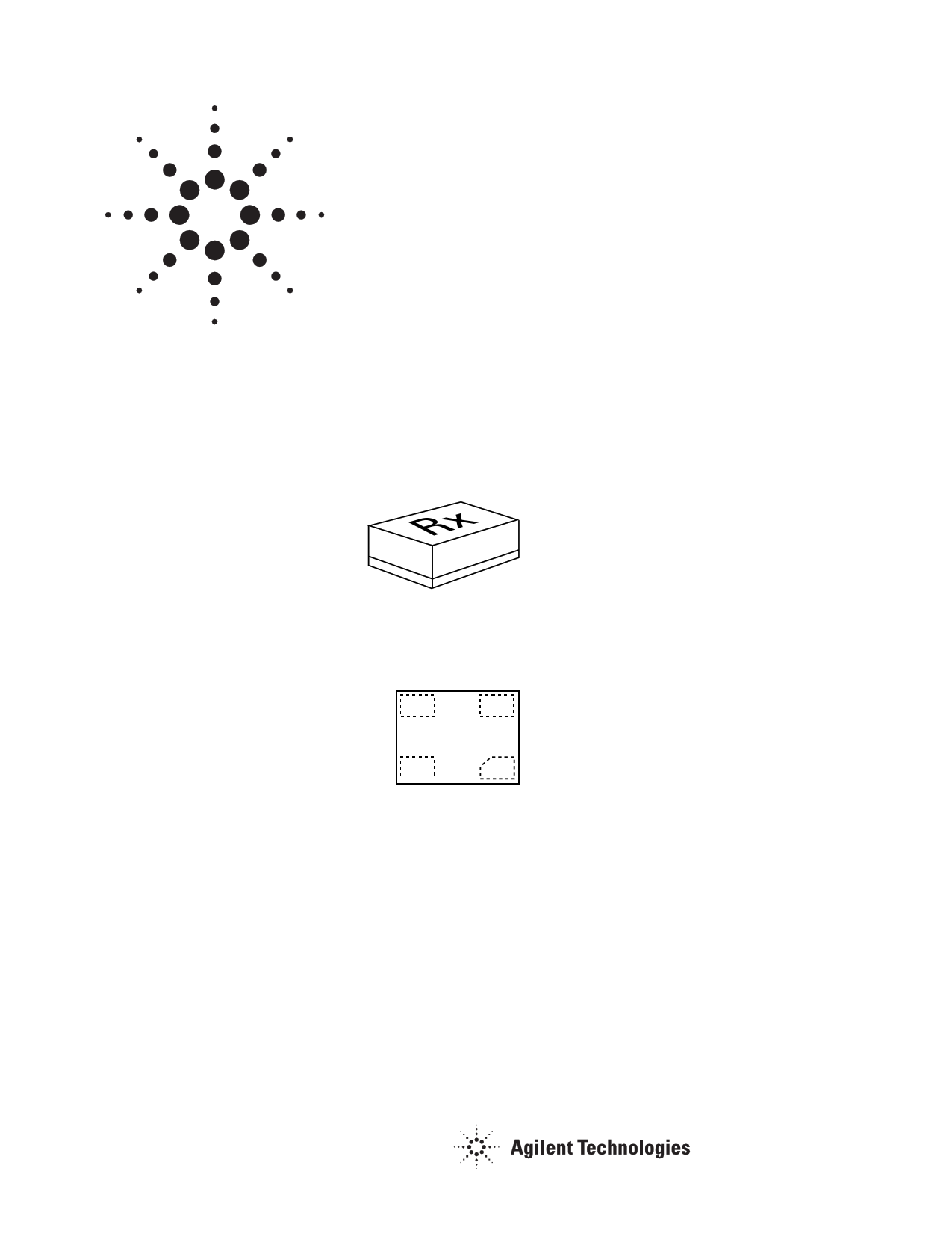
MiniPak 1.4 mm x 1.2 mm Package
Rx
Pin Connections and
Package Marking
Source
Pin 3
Gate
Pin 2
Rx
Drain
Pin 4
Source
Pin 1
Note:
Top View. Package marking provides orientation,
product identification and date code.
“R” = Device Type Code
“x” = Date code character. A different
character is assigned for each month and
year.
Features
• High linearity performance
• Single Supply Enhancement Mode
Technology[1]
• Very low noise figure
• Excellent uniformity in product
specifications
• 800 micron gate width
• Miniature leadless package
1.4 mm x 1.2 mm x 0.7 mm
• Tape-and-Reel packaging option
available
Specifications
2 GHz; 3V, 60 mA (Typ.)
• 35.8 dBm output 3rd order intercept
• 21.4 dBm output power at 1 dB gain
compression
• 0.5 dB noise figure
• 17.5 dB associated gain
Applications
• Low Noise Amplifier and Driver
Amplifier for Cellular/PCS and
WCDMA Base Stations
• LNA and Driver Amplifier for
WLAN, WLL/RLL and MMDS
applications
• General purpose discrete E-PHEMT
for ultra low noise applications in
the 450 MHz to 10 GHz frequency
range
Note:
1. Enhancement mode technology requires
positive Vgs, thereby eliminating the need for
the negative gate voltage associated with
conventional depletion mode devices.
1 page 
ATF-541M4 Typical Performance Curves, continued
30 45
25°C
25
-40°C
85°C
40
35
20
30
15
25
10
20
25°C
-40°C
85°C
5 15
0
01 2 3 4 5 67
FREQUENCY (GHz)
Figure 12. Gain vs. Freq. and Temperature
Tuned for Max OIP3 and Min NF at
Vds = 3V, Ids = 60 mA[1].
10
01 2 3 4 5 67
FREQUENCY (GHz)
Figure 13. OIP3 vs. Freq. and Temperature
Tuned for Max OIP3 and Min NF at
Vds = 3V, Ids = 60 mA[1].
2.0
25°C
-40°C
1.5 85°C
1.0
0.5
0
01 2 3 4 5 67
FREQUENCY (GHz)
Figure 14. NF vs. Freq. and Temperature
Tuned for Max OIP3 and Min NF at
Vds = 3V, Ids = 60 mA[1].
23
25°C
22
-40°C
85°C
21
20
19
18
17
01 2 3 4 5 67
FREQUENCY (GHz)
Figure 15. P1dB vs. Freq. and Temperature
Tuned for Max OIP3 and Min NF at
Vds = 3V, Ids = 60 mA[1].
ATF-541M4 Output Reflection Coefficient Parameters Tuned
for Maximum Output IP3[1]; VDS = 3V, IDS = 60 mA
Freq
(GHz)
Gamma[2]
Out_Mag.
(Mag)
Gamma[2]
Out_Mag.
(Degrees)
OIP3
(dBm)
P1dB
(dBm)
0.9 0.006
2.0 0.314
3.9 0.321
5.8 0.027
23
-167
134
89
35.04
35.82
36.60
37.62
19.47
21.36
20.37
19.38
Notes:
1. Input tuned for minimum NF and the output tuned for maximum OIP3
using an InterContinental Microwave (ICM) test fixture, double stub
tuners and bias tees.
2. Gamma out is the reflection coefficient of the matching circuit presented
to the output of the device.
5
5 Page 
briefly elevates the temperature
sufficiently to produce a reflow
of the solder.
The recommended lead-free
reflow profile is shown in Fig-
ure 22.
The rates of change of tempera-
ture for the ramp-up and cool-
down zones are chosen to be low
enough to not cause deformation
of board or damage to compo-
nents due to thermal shock. The
maximum temperature in the
reflow zone (Tmax) should not
exceed 235°C for leaded solder.
These parameters are typical for
a surface mount assembly
process for the ATF-541M4. As a
general guideline, the circuit
board and components should
only be exposed to the minimum
temperatures and times the
necessary to achieve a uniform
reflow of solder.
Electrostatic Sensitivity
FETs and RFICs are electrostatic
discharge (ESD) sensitive de-
vices. Agilent devices are manu-
factured using a very robust and
reliable PHEMT process, however,
permanent damage may occur to
these devices if they are sub-
jected to high-energy electrostatic
discharges. Electrostatic charges
as high as several thousand volts
(which readily accumulate on the
human body and on test equip-
ment) can discharge without
detection and may result in
failure or degradation in perfor-
mance and reliability.
250
TMAX
200
150
Reflow
Zone
100
Preheat
Zone
Cool Down
Zone
50
0
0 60
Figure 21. Leaded Solder Reflow Profile.
120 180
TIME (seconds)
240
300
Electronic devices may be
subjected to ESD damage in any
of the following areas:
• Storage & handling
• Inspection
• Assembly & testing
• In-circuit use
The ATF-541M4 is an ESD Class 1
device. Therefore, proper ESD
precautions are recommended
when handling, inspecting,
testing, and assembling these
devices to avoid damage.
Any user-accessible points in
wireless equipment (e.g. antenna
or battery terminals) provide an
opportunity for ESD damage.
For circuit applications in which
the ATF-541M4 is used as an
input or output stage with close
coupling to an external antenna,
the device should be protected
from high voltage spikes due to
human contact with the antenna.
A good practice, illustrated in
Figure 23, is to place a shunt
inductor or RF choke at the
antenna connection to protect
the receiver and transmitter
circuits. It is often advantageous
to integrate the RF choke into the
design of the diplexer or T/R
switch control circuitry.
350
Peak Temperature
300 Min. 240°C
Max. 255°C
250
221
200 Reflow Time
Min. 60s
150 Max. 90s
100 Preheat 130 – 170°C
Min. 60s
50 Max. 150s
0
0 30 60 90 120 150 180 210 240 270 300 330 360
TIME (seconds)
Figure 22. Lead-free Solder Reflow Profile.
11
Figure 23. In-circuit ESD Protection.
11 Page | ||
| Páginas | Total 16 Páginas | |
| PDF Descargar | [ Datasheet ATF-541M4.PDF ] | |
Hoja de datos destacado
| Número de pieza | Descripción | Fabricantes |
| ATF-541M4 | Low Noise Enhancement Mode Pseudomorphic HEMT | Agilent |
| ATF-541M4 | Low Noise Enhancement Mode Pseudomorphic HEMT | AVAGO |
| Número de pieza | Descripción | Fabricantes |
| SLA6805M | High Voltage 3 phase Motor Driver IC. |
Sanken |
| SDC1742 | 12- and 14-Bit Hybrid Synchro / Resolver-to-Digital Converters. |
Analog Devices |
|
DataSheet.es es una pagina web que funciona como un repositorio de manuales o hoja de datos de muchos de los productos más populares, |
| DataSheet.es | 2020 | Privacy Policy | Contacto | Buscar |