|
|
|
PDF DN8899UAS Data sheet ( Hoja de datos )
| Número de pieza | DN8899UAS | |
| Descripción | Hall IC | |
| Fabricantes | Panasonic | |
| Logotipo | ||
Hay una vista previa y un enlace de descarga de DN8899UAS (archivo pdf) en la parte inferior de esta página. Total 6 Páginas | ||
|
No Preview Available !
Hall ICs
DN8899UAS
Hall IC for alternative magnetic field (SOH-4D type)
s Overview
The DN8899UAS is a Hall IC in which a Hall element,
an amplifier circuit, Schmidt circuit, stabilized power sup-
ply and temperature compensation circuit are integrated
onto a single chip using IC technology. It amplifies Hall
element output in the amplifier and converts it into a digital
signal through the Schmidt circuit so as to drive the TTL
or MOS IC directly.
The characterisitcs are guaranteed at a normal tem-
perature (25°C) and a high temparature (135°C).
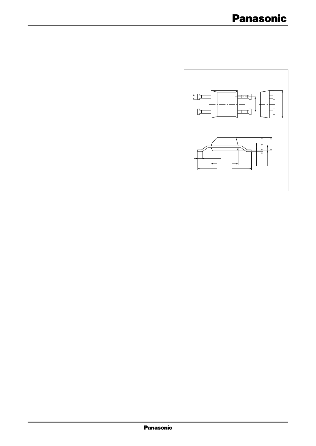
Unit: mm
14
23
s Features
0.4±0.15
• The characterisitcs are tested and guaranteed at a nor-
mal temperature (25°C) and a high temparature (135°C)
3.0±0.3
5.4±0.4
for all devices.
• High sensitivity and low drift
ESOP004-P-0200
• Stable temperature characteristics due to the built-in tem-
perature compensation circuit
• Wide operating supply voltage range (VCC = 4.5 V to 16 V)
• Operating in alternative magnetic field
• Direct drivability of TTL and MOS ICs with output
• Open collector output
• The hysteresis width of the zero-cross type includes "0" tesla point.
• Operation magnetic flux density does not depend on the supply voltage due to the built-in stabilization power supply.
• Surface mount package
s Applications
• Speed sensor, position sensor, rotation sensor, key board switch and micro switch etc.
1
1 page 
Hall ICs
DN8899UAS
s Caution on use of Hall ICs
As the Hall IC is often used to detect movement, the position of a Hall IC may be changed, and there is the risk of
a change in detection level, if exposed to shock or vibration over a long period of time. Secure the IC by applying
adhesive to the package or placing in a dedicated case.
1. On mounting of the surface mount type (ESO004-P-0200 package)
Set pin 2 to open or connect to GND. It will be damaged if it is connected to VCC . When mounted on the printed
circuit board, the Hall IC may be highly stressed by the warp that may occur from the soldering. This may also cause
a change in the operating magnetic flux density and a deterioration of its resistance to moisture.
Be cautious to keep the device from being stressed thermally or mechanically up to the 2 mm distance from the
package.
2. On using flux in soldering
Choose a flux which does not include ingredients from halogen group, such as chlorine, fluorine, etc. The
ingredients of halogen group may enter where the lead frame and package resin joint, causing corrosion and the
disconnection of the aluminum wiring on the surface of an IC chip.
3. On fixing a Hall IC with the holder
When a Hall IC is mounted on the printed circuit board with a holder and the coefficient of expansion of the holder
is large, the lead wire of the Hall IC will be stretched and it may give a stress to the Hall IC.
If the lead wire is stressed intensely due to the distortion of holder or board, the adhesives between the package
and the lead wire may be weakened and cause a minute gap resulting in the deterioration of its resistance to moisture.
Sensitivity may also be changed by this stress.
4. Power supply line/power transmission line
If a power supply line/power transmission line becomes longer, noise and/or oscillation may be found on the line.
In this case, set the capacitor of 0.1 µF to 10 µF near a Hall IC to prevent it.
If a voltage of 18 V or more is thought to be applied to the power supply line (flyback voltage from coil or the
ignition pulse, etc.), avoid it with external components (capacitor, resistor, Zener diode, diode, surge absorbing ele-
ments, etc.).
5. VCC and GND
Do not reverse VCC and GND. If the VCC and GND pins are reversely connected, this IC will be destroyed. If the
IC GND-pin voltage is set higher than other pin voltage, the IC configuration will become same as a forward biased
diode. Therefore, it will turn on at the diode forward voltage (approximately 0.7 V), and a large current will flow
through the IC, ending up in its destruction. (This is common to Monolithic IC.)
6. Cautions on power ON of Hall IC
When a Hall IC is turned ON, the position of the magnet or looseness may change the output of a Hall IC, and a
pulse may be generated. Therefore, care should be given whenever the output state of a Hall IC is critical when the
supply power is ON.
7. When magnetic force of magnet is too strong
Output may be inverted when applying a magnetic flux density of 100mT or more. Accordingly, magnetic flux
density should be used within the range of 100 mT.
5
5 Page | ||
| Páginas | Total 6 Páginas | |
| PDF Descargar | [ Datasheet DN8899UAS.PDF ] | |
Hoja de datos destacado
| Número de pieza | Descripción | Fabricantes |
| DN8899UAS | Hall IC | Panasonic |
| Número de pieza | Descripción | Fabricantes |
| SLA6805M | High Voltage 3 phase Motor Driver IC. |
Sanken |
| SDC1742 | 12- and 14-Bit Hybrid Synchro / Resolver-to-Digital Converters. |
Analog Devices |
|
DataSheet.es es una pagina web que funciona como un repositorio de manuales o hoja de datos de muchos de los productos más populares, |
| DataSheet.es | 2020 | Privacy Policy | Contacto | Buscar |