|
|
|
PDF BD7682FJ-LB Data sheet ( Hoja de datos )
| Número de pieza | BD7682FJ-LB | |
| Descripción | Low Noise Quasi-Resonant Control DC/DC converter IC | |
| Fabricantes | ROHM Semiconductor | |
| Logotipo | ||
Hay una vista previa y un enlace de descarga de BD7682FJ-LB (archivo pdf) en la parte inferior de esta página. Total 30 Páginas | ||
|
No Preview Available !
Datasheet
Low Noise Quasi-Resonant Control
DC/DC converter IC for AC/DC Converter
BD7682FJ-LB BD7683FJ-LB BD7684FJ-LB BD7685FJ-LB
General Description
This is the product guarantees long time support in the
Industrial market.
BD768xFJ series is a Quasi-resonant controller type
DC/DC converters that provide an optimum system for
all products that include an electrical outlet.
Quasi-resonant operation enables soft switching and
helps to keep EMI low. Design with a high degree of
flexibility is achieved with switching MOSFETs and
current detection resistors as external devices.
The built-in brown out function monitors the input
voltage as part of system optimization. The burst mode
function reduces input power at low power.
BD768xFJ series include various protection functions,
such as a soft start function, burst function, per-cycle
over-current limiter function, overvoltage protection
function, overload protection function, and brown out
function.
BD768xFJ series include a gate-clamp circuit for
optimal driving SIC-MOSFET.
Features
Pin 8 : SOP-J8 Package
(6.00mm × 4.90mm : 1.27mm pitch <TYP>)
Quasi-resonant type (low EMI)
Frequency reduction mode
Low current consumption (19µA), during standby
Low current consumption when no load (burst
operation when light load)
Maximum frequency (120kHz)
CS Pin Leading-Edge Blanking
VCC UVLO (Under Voltage Drop Out protection)
VCC OVP (Over Voltage Protection)
Per-cycle over-current protection circuit
Soft start
ZT trigger mask function
Voltage protection function (brown out)
ZT OVP (Over Voltage Protection)
Gate-clamp circuit
Key Specifications
Operating Power Supply Voltage Range:
VCC 15.0V to 27.5V
Normal Operating Current:
0.80mA(Typ)
Burst Operating Current:
0.50mA(Typ)
Maximum Frequency:
120kHz(Typ)
Operating Temperature:
-40°C to +105°C
Package 4.90mm x 6.00mm x 1.65mm pitch 1.27mm
(Typ.) (Typ.)
(TYP.)
(TYP.)
SOP-J8
4.90mm x 6.00mm x 1.65mm
Lineup
BD7682FJ
BD7683FJ
BD7684FJ
BD7685FJ
FBOLP
AutoRestart
Latch
AutoRestart
Latch
VCCOVP
Latch
Latch
AutoRestart
AutoRestart
Applications
Industrial equipment, AC Adaptor, Household appliances
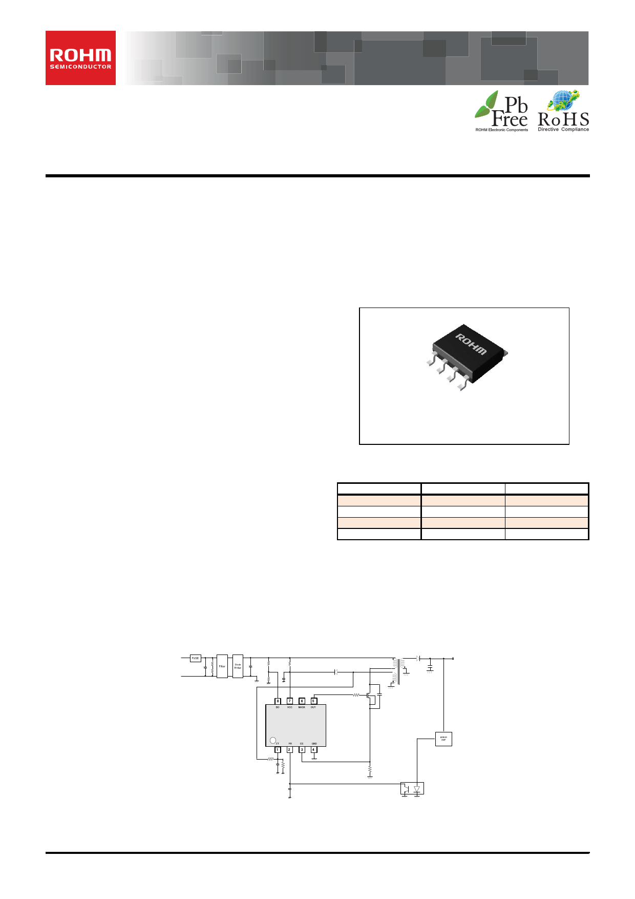
Typical Application Circuit
○Product structure:Silicon monolithic integrated circuit
.www.rohm.com
© 2015 ROHM Co., Ltd. All rights reserved.
TSZ22111・14・001
○This product has no designed protection against radioactive rays
1/27
TSZ02201-0F1F0A200050-1-2
17.Apr.2015. Rev.001
1 page 
BD768xFJ-LB Series
Application Information
Description of Blocks
(1) Start-Up sequences (FBOLP:auto recovery mode)
The BD768xFJ’s start up sequence is shown in Figure 1.
See the sections below for detailed descriptions.
Datasheet
VH
BO 1.0V
19.5V
VCC
Internal REF
Pull Up
128msec
FB
14.0V
128msec
128msec
Volp1
Vout
Iout
Normal
Load
Light
LOAD
Over
Load
Burst mode
Switching
Soft
Start
A
BC D
E
F GH
IJ K
Figure 1. Start-up Sequence Timing Chart
A: Input voltage VH is applied
B: VCC pin voltage rises due to start resistor RSTART, and this IC starts operating when VCC > VUVLO1 (19.5V typ).
Switching starts when the status of the brown out function is normal (BO > 1.0 V), other protection functions are also
considered normal. At that time, the VCC value always drops due to the pin's consumption current, so VCC > VUVLO2
(14.0 V typ) should be set.
C: There is a soft start function which regulates the voltage level at the CS pin to prevent a rise in voltage and current.
D: When the switching operation starts, VOUT rises.
Once the output voltage starts, set the rated voltage to within the TFOLP period (128ms typ).
E: When there is a light load, burst operation is order to keep power consumption down.
F: Overload operation.
G: When the FB pin voltage keeps FB > VFOLP1 (=2.8V typ) at or above TFOLP (128ms typ), switching is stopped by the
overload protection circuit.
If the FB pin voltage status becomes FB < VFOLP1B even once, the IC’s internal 128ms timer is reset.
H: If the VCC voltage drops to VCC < VUVLO2 (14.0V typ) or below, restart is executed.
I: The IC’s circuit current is reduced and the VCC pin value rises. (Same as B)
J: Same as F
K: Same as G
Start resistance RSTART is the resistance required to start the IC.
When the start resistance RSTART value is reduced, standby power is increased and the startup time is shortened.
Conversely, when the start resistance RSTART value is increased, standby power is reduced and the startup time is
lengthened.
When BD768xFJ is in standby mode, current IOFF becomes 30µA Max
However, this is the minimum current required to start the IC. Use the appropriate current for the set target.
Example: Start Resistance RSTART Setting
RSTART VMIN VUVLO max / IOFF
When VAC = 100 V, if the margin is -20%, then VMIN = 113V
Since VUVLO1 (max) = 20.0V,
And since RSTART < (113-20) / 30µA = 3.10 MΩ, the start resistance is 3.0MΩ. (Set according to the start time.)
In this case: RSTART power consumption Pd RSTART VH VCC 2 / RSTART 141V 14V2 / 3.0M 5.4mW
www.rohm.com
© 2015 ROHM Co., Ltd. All rights reserved.
TSZ22111・15・001
5/27
TSZ02201-0F1F0A200050-1-2
17.Apr.2015. Rev.001
5 Page 
BD768xFJ-LB Series
Datasheet
VLIM1
VLIM1 * 0.8
Figure 7. CS Switching: FB Voltage vs CS Voltage
IZT [mA]
Figure 8. CS Switching: ZT Current vs CS Voltage
Example: Setup method (for switching between 100-V AC and 220-V AC.)
100-V AC: 141V ±42V (±30% margin)
220-V AC: 308V ±62V (±20% margin)
In the above cases, the CS current is switched in the range from 182V to 246V. This is done when => VH =
214 VH.
Given: Np = 100, Na = 15.
Va VIN * Na / Np 214V * 15 / 100 * 1 32.1V
RZC Va / IZT 32.1V / 1mA 32.1kΩ
According to the above, RZT = 32 KΩ is set.
CS
Limiter[V] Y
Vlim1
Vlim1*0.7
214V
Figure 9. CS Switching: VH Voltage vs CS Voltage
X
VH[V]
www.rohm.com
© 2015 ROHM Co., Ltd. All rights reserved.
TSZ22111・15・001
11/27
TSZ02201-0F1F0A200050-1-2
17.Apr.2015. Rev.001
11 Page | ||
| Páginas | Total 30 Páginas | |
| PDF Descargar | [ Datasheet BD7682FJ-LB.PDF ] | |
Hoja de datos destacado
| Número de pieza | Descripción | Fabricantes |
| BD7682FJ-LB | Low Noise Quasi-Resonant Control DC/DC converter IC | ROHM Semiconductor |
| Número de pieza | Descripción | Fabricantes |
| SLA6805M | High Voltage 3 phase Motor Driver IC. |
Sanken |
| SDC1742 | 12- and 14-Bit Hybrid Synchro / Resolver-to-Digital Converters. |
Analog Devices |
|
DataSheet.es es una pagina web que funciona como un repositorio de manuales o hoja de datos de muchos de los productos más populares, |
| DataSheet.es | 2020 | Privacy Policy | Contacto | Buscar |