|
|
|
PDF NGD8205NT4G Data sheet ( Hoja de datos )
| Número de pieza | NGD8205NT4G | |
| Descripción | Ignition IGBT | |
| Fabricantes | ON Semiconductor | |
| Logotipo | ||
Hay una vista previa y un enlace de descarga de NGD8205NT4G (archivo pdf) en la parte inferior de esta página. Total 7 Páginas | ||
|
No Preview Available !
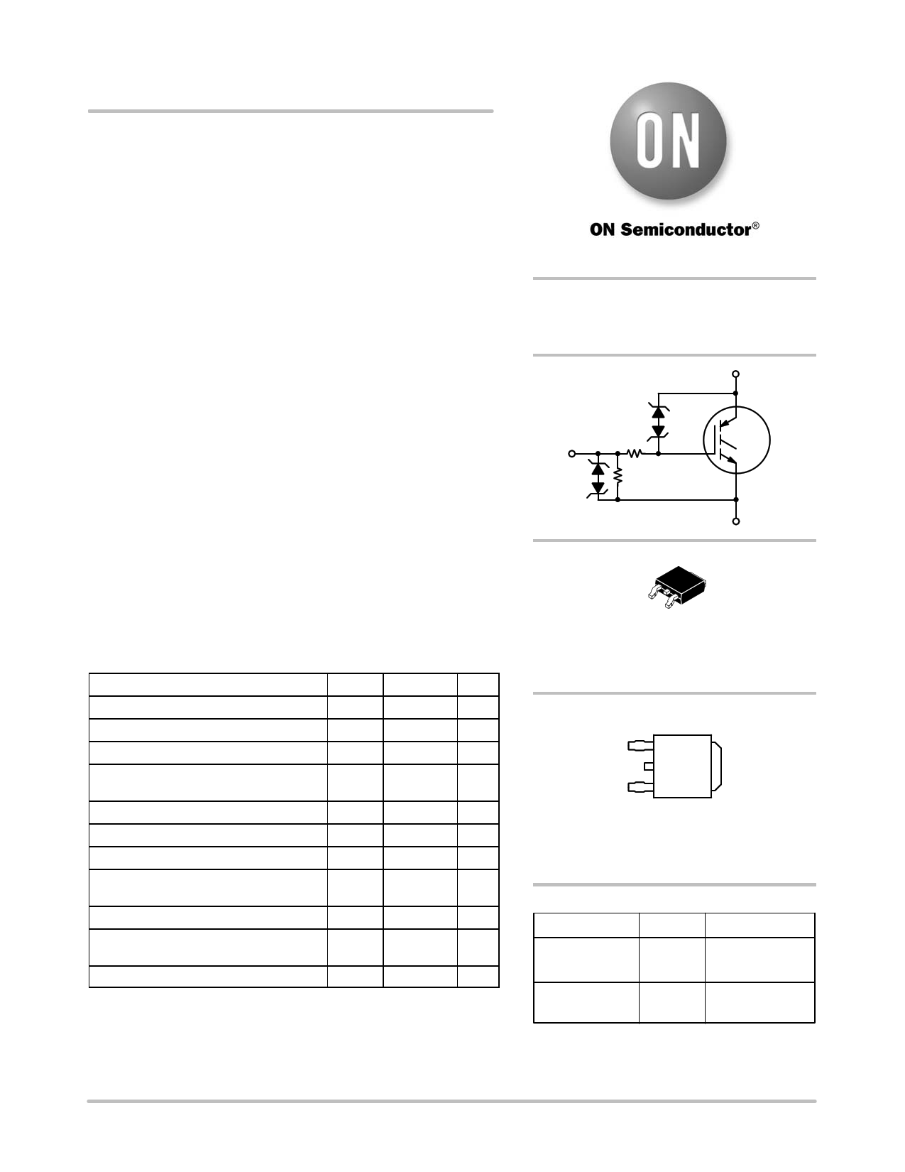
NGD8205N, NGD8205AN
Ignition IGBT
20 Amp, 350 Volt, N−Channel DPAK
This Logic Level Insulated Gate Bipolar Transistor (IGBT) features
monolithic circuitry integrating ESD and Overvoltage clamped
protection for use in inductive coil drivers applications. Primary uses
include Ignition, Direct Fuel Injection, or wherever high voltage and
high current switching is required.
Features
• Ideal for Coil−on−Plug and Driver−on−Coil Applications
• DPAK Package Offers Smaller Footprint for Increased Board Space
• Gate−Emitter ESD Protection
• Temperature Compensated Gate−Collector Voltage Clamp Limits
Stress Applied to Load
• Integrated ESD Diode Protection
• Low Threshold Voltage for Interfacing Power Loads to Logic or
Microprocessor Devices
• Low Saturation Voltage
• High Pulsed Current Capability
• Optional Gate Resistor (RG) and Gate−Emitter Resistor (RGE)
• These are Pb−Free Devices
Applications
• Ignition Systems
MAXIMUM RATINGS (TJ = 25°C unless otherwise noted)
Rating
Symbol Value
Unit
Collector−Emitter Voltage
Collector−Gate Voltage
Gate−Emitter Voltage
Collector Current−Continuous
@ TC = 25°C − Pulsed
VCES
VCER
VGE
IC
390
390
"15
20
50
V
V
V
ADC
AAC
Continuous Gate Current
Transient Gate Current (t≤2 ms, f≤100 Hz)
ESD (Charged−Device Model)
IG
IG
ESD
1.0 mA
20 mA
2.0 kV
ESD (Human Body Model)
R = 1500 W, C = 100 pF
ESD
kV
8.0
ESD (Machine Model) R = 0 W, C = 200 pF ESD 400 V
Total Power Dissipation @ TC = 25°C
Derate above 25°C
PD 125 W
0.83 W/°C
Operating & Storage Temperature Range TJ, Tstg −55 to +175 °C
Stresses exceeding Maximum Ratings may damage the device. Maximum
Ratings are stress ratings only. Functional operation above the Recommended
Operating Conditions is not implied. Extended exposure to stresses above the
Recommended Operating Conditions may affect device reliability.
© Semiconductor Components Industries, LLC, 2012
January, 2012 − Rev. 9
1
http://onsemi.com
20 A, 350 V
VCE(on) = 1.3 V @
IC = 10 A, VGE . 4.5 V
C
G RG
RGE
E
4
12
3
DPAK
CASE 369C
STYLE 7
MARKING DIAGRAM
1
G
C
E
YWW
NGD
8205xG
C
Y
WW
NGD8205x
x
G
= Year
= Work Week
= Device Code
= N or A
= Pb−Free Package
ORDERING INFORMATION
Device
Package
Shipping†
NGD8205NT4G
DPAK 2500 / Tape & Reel
(Pb−Free)
NGD8205ANT4G DPAK 2500 / Tape & Reel
(Pb−Free)
†For information on tape and reel specifications,
including part orientation and tape sizes, please
refer to our Tape and Reel Packaging Specification
Brochure, BRD8011/D.
Publication Order Number:
NGD8205N/D
1 page 
NGD8205N, NGD8205AN
TYPICAL ELECTRICAL CHARACTERISTICS
45
40 VCE = 5 V
35
30
25
20
15 TJ = 25°C
10
5 TJ = 175°C
0 TJ = −40°C
0 0.5 1 1.5 2 2.5 3 3.5
VGE, GATE TO EMITTER VOLTAGE (V)
Figure 7. Transfer Characteristics
100000
10000
1000
VCE = −24 V
100
10 VCE = 175 V
1.0
0.1
4 −50 −25 0 25 50 75 100 125 150 175
TJ, JUNCTION TEMPERATURE (°C)
Figure 8. Collector−to−Emitter Leakage
Current vs. Temperature
2.50
2.25
2.00
Mean + 4 s
Mean
1.75
1.50 Mean − 4 s
1.25
1.00
0.75
0.50
0.25
−050 −25 0 25 50 75 100 125 150 175
TJ, JUNCTION TEMPERATURE (°C)
10000
1000
100
10
1.0
0.1
0
Figure 9. Gate Threshold Voltage vs.
Temperature
Ciss
Coss
Crss
5
10 15
20
VCE, COLLECTOR TO EMITTER VOLTAGE (V)
Figure 10. Capacitance vs.
Collector−to−Emitter Voltage
25
12
10 tfall
8
tdelay
6
VCC = 300 V
4 VGE = 5.0 V
RG = 1000 W
2 IC = 9.0 A
RL = 33 W
0
25 50 75 100 125 150 175
TJ, JUNCTION TEMPERATURE (°C)
Figure 11. Resistive Switching Fall Time vs.
Temperature
12
VCC = 300 V
10 VGE = 5.0 V
RG = 1000 W
8
IC = 9.0 A
L = 300 mH
6
4
tdelay
tfall
2
0
25 50 75 100 125 150 175
TJ, JUNCTION TEMPERATURE (°C)
Figure 12. Inductive Switching Fall Time vs.
Temperature
http://onsemi.com
5
5 Page | ||
| Páginas | Total 7 Páginas | |
| PDF Descargar | [ Datasheet NGD8205NT4G.PDF ] | |
Hoja de datos destacado
| Número de pieza | Descripción | Fabricantes |
| NGD8205NT4G | Ignition IGBT | ON Semiconductor |
| Número de pieza | Descripción | Fabricantes |
| SLA6805M | High Voltage 3 phase Motor Driver IC. |
Sanken |
| SDC1742 | 12- and 14-Bit Hybrid Synchro / Resolver-to-Digital Converters. |
Analog Devices |
|
DataSheet.es es una pagina web que funciona como un repositorio de manuales o hoja de datos de muchos de los productos más populares, |
| DataSheet.es | 2020 | Privacy Policy | Contacto | Buscar |