|
|
|
PDF PS22054 Data sheet ( Hoja de datos )
| Número de pieza | PS22054 | |
| Descripción | Dual-In-Line Intelligent Power Module | |
| Fabricantes | Powerex | |
| Logotipo | ||
Hay una vista previa y un enlace de descarga de PS22054 (archivo pdf) en la parte inferior de esta página. Total 10 Páginas | ||
|
No Preview Available !
PS22054
Powerex, Inc., 200 E. Hillis Street, Youngwood, Pennsylvania 15697-1800 (724) 925-7272
Intellimod™ Module
Dual-In-Line Intelligent
Power Module
15 Amperes/1200 Volts
A
D
K
12
34
56
78
9 10
11 12 13 14 15 16 17 18 19 20 21
DETAIL "A"
LABEL
BG
UL
22 23 24 25 26 27 28
HEATSINK
SIDE
E
HJ
F
M
DETAIL "B"
O
N
DETAIL "C"
DETAIL "A"
HEATSINK SIDE
V
W
30°
AA Z
X
Y
C
P
0 ~ 5°
Q
V
CC
EE
DD
30°
Z AA
BB
DETAIL "B"
DETAIL "C"
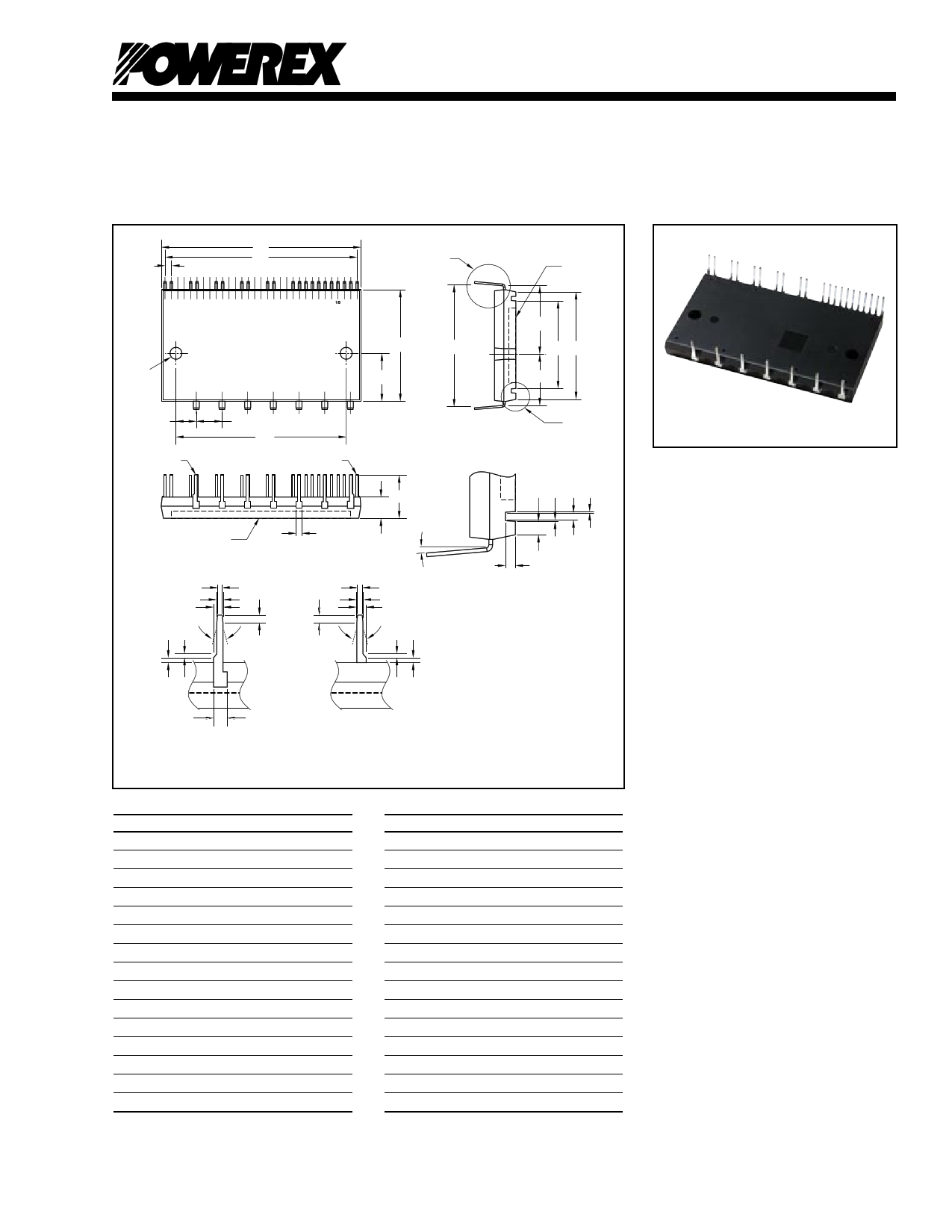
LEADS THICKNESS = 0.7mm
ALL TERMINALS TREATED BY Pb-FREE SOLDER PLATING
RS TS
R
DETAIL "A"
TERMINAL CODE
1 VUFS
2 VUFB
3 VP1
4 UP
5 VVFS
6 VVFB
7 VP1
8 VP
9 VWFS
10 VWFB
11 VP1
12 VPC
13 WP
14 VN1
15 VNC
16 CIN
17 CFO
18 FO
19 UN
20 VN
21 WN
22 P
23 U
24 V
25 W
26 NU
27 NV
28 NW
Outline Drawing and Circuit Diagram
Dimensions
Inches
Millimeters
A 3.11±0.02 79.0±0.5
B 1.73±0.02 44.0±0.5
C 0.63±0.01 16.1±0.3
D 3.0 76.2
E 1.08±0.02 27.4±0.5
F 0.80±0.02 20.4±0.5
G 1.91±0.02 48.6±0.5
H 1.34±0.02 34.0±0.5
J 1.67±0.02 42.5±0.5
K 0.10±0.01 2.54±0.3
L 0.73±0.02 18.5±0.5
M
0.31±0.01
8.0±0.3
N 2.64±0.01 67.0±0.3
O 0.40±0.01 10.16±0.3
P
0.32±0.02
8.2±0.5
Dimensions
Inches
Millimeters
Q 0.09 2.5
R 0.08 2.0
S 0.01 0.3
T 0.07 1.7
U 0.18±0.008 Dia. 4.5±0.2 Dia.
V
0.024
0.6
W 0.039±0.008 1.0±0.2
X 0.06±0.008 1.5±0.2
Y 0.05 1.2
Z 0.02 0.5
AA 0.024±0.02 0.6±0.5
BB 0.098 2.5
CC 0.031±0.008 0.8±0.2
DD 0.051±0.008 1.3±0.2
EE 0.04 1.0
Description:
DIP-IPMs are intelligent power
modules that integrate power
devices, drivers, and protection
circuitry in an ultra compact
dual-in-line transfer-mold package
for use in driving small three
phase motors. Use of 4th
generation IGBTs, DIP packaging,
and application specific HVICs
allow the designer to reduce
inverter size and overall design
time.
Features:
£ Compact Packages
£ Single Power Supply
£ Integrated HVICs
£ Direct Connection to CPU
Applications:
£ Washing Machines
£ Refrigerators
£ Air Conditioners
£ Small Servo Motors
£ Small Motor Control
Ordering Information:
PS22054 is a 1200V, 15 Ampere
DIP Intelligent Power Module.
Rev. 10/05
1
1 page 
Powerex, Inc., 200 E. Hillis Street, Youngwood, Pennsylvania 15697-1800 (724) 925-7272
PS22054
Intellimod™ Module
Dual-In-Line Intelligent Power Module
15 Amperes/1200 Volts
Application Circuit
+15V
R2 x 3
+5V
R3
C5 x 3 C4
C3 + C2
R2 C5
C2
D1
+
R1 C1
C2
RSF
CSF
21
WN
VN
UN
FO
CFO
CIN
VNC
VN1
WP
VPC
INPUT SIGNAL
CONDITIONING
FAULT
LOGIC
UV
PROT.
+VCC
LVIC
VP1
VWFB
VWFS
28
NW
NV
RSHUNT
NU
This symbol
indicates
connection to
ground plane.
W
R2 C5
D1 C2
+
R1 C1
C2
VP
VP1
VVFB
VVFS
R2 C5
D1 C2
+
R1 C1
C2
UP
VP1
VUFB
VUFS
1
MOTOR
V
U
C6
C7 +
C6
P+
22
Component Selection:
Dsgn.
Typ. Value
D1
C1
C2
C3
C4
C5
C6
C7
CSF
RSF
RSHUNT
R1
R2
R3
1A, 1200V
10-100uF, 50V
0.22-2.0uF, 50V
10-100uF, 50V
22nF, 50V
100pF, 50V
200-2000uF, 450V
0.1-0.22uF, 1000V
1000pF, 50V
1.8k ohm
5-100 mohm
10 ohm
330 ohm
10k ohm
Description
Boot strap supply diode – Ultra fast recovery
Boot strap supply reservoir – Electrolytic, long life, low impedance, 105°C (Note 5)
Local decoupling/High frequency noise filters – Multilayer ceramic (Note 8)
Control power supply filter – Electrolytic, long life, low Impedance, 105°C
Fault lock-out timing capacitor – Multilayer ceramic (Note 4)
Optional input signal noise filter – Multilayer ceramic (Note 1)
Main DC bus filter capacitor – Electrolytic, long life, high ripple current, 105°C
Surge voltage suppression capacitor – Polyester/polypropylene film (Note 9)
Short circuit detection filter capacitor – Multilayer ceramic (Note 6, Note 7)
Short circuit detection filter resistor (Note 6, Note 7)
Current sensing resistor – Non-inductive, temperature stable, tight tolerance (Note 10)
Boot strap supply inrush limiting resistor (Note 5)
Optional control input noise filter (Note 1, Note 2)
Fault output signal pull-up resistor (Note 3)
Notes:
1) To prevent input signal oscillations minimize wiring length to controller (~2cm). Additional RC filtering (C5 etc.) may be
required. If filtering is added be careful to maintain proper dead time and voltage levels. See application notes for details.
2) Internal HVIC provides high voltage level shifting allowing direct connection of all six driving signals to the controller.
3)
4)
FO
C4
output is an open collector type. Pull up resistor (R3) should be adjusted
sets the fault output duration and lock-out time. C4 ≈ 9.3E-6 x tFO, 22nF
to current sink
gives ~2.4ms.
capability
of
the
controller.
5) Boot strap supply component values must be adjusted depending on the PWM frequency and technique.
6) Wiring length associated with RSHUNT, RSF, CSF must be minimized to avoid improper operation of the OC function.
7) RSF, CSF set over circuit protection trip time. Recommend time constant is 1.5us-2.0us. See application notes.
8) Local decoupling/high frequency filter capacitors must be connected as close as possible to the modules pins.
9) The length of the DC link wiring between C6, C7, the DIP’s P terminal and the shunt must be minimized to prevent
excessive transient voltages. In particular, C7 should be mounted as close to the DIP as possible.
10) Use a high quality, tight tolorance current sensing resistor. Connect resistor as close as possible to the DIP’s
N terminal. Be careful to check for proper power rating. See application notes for calculation of resistance value.
Rev. 10/05
AC LINE
5
5 Page | ||
| Páginas | Total 10 Páginas | |
| PDF Descargar | [ Datasheet PS22054.PDF ] | |
Hoja de datos destacado
| Número de pieza | Descripción | Fabricantes |
| PS22053 | Module Dual-In-Line Intelligent Power Module 10 Amperes/1200 Volt | Powerex |
| PS22053 | 1200V/10A low-loss 4th generation IGBT inverter bridge | Mitsubishi Electric Semiconductor |
| PS22054 | Dual-In-Line Intelligent Power Module | Powerex |
| Número de pieza | Descripción | Fabricantes |
| SLA6805M | High Voltage 3 phase Motor Driver IC. |
Sanken |
| SDC1742 | 12- and 14-Bit Hybrid Synchro / Resolver-to-Digital Converters. |
Analog Devices |
|
DataSheet.es es una pagina web que funciona como un repositorio de manuales o hoja de datos de muchos de los productos más populares, |
| DataSheet.es | 2020 | Privacy Policy | Contacto | Buscar |