|
|
|
PDF IN89C2051 Data sheet ( Hoja de datos )
| Número de pieza | IN89C2051 | |
| Descripción | 8-BIT MICROCONTROLLER | |
| Fabricantes | Integral | |
| Logotipo | ||
Hay una vista previa y un enlace de descarga de IN89C2051 (archivo pdf) en la parte inferior de esta página. Total 13 Páginas | ||
|
No Preview Available !
IN89C2051
8-BIT MICROCONTROLLER WITH 2K BYTES FLASH
Description
The IN89C2051 is a low-voltage, high-performance CMOS 8-bit microcomputer with
2K Bytes of Flash programmable and erasable read only memory (PEROM). The device is
manufactured using Atmel’s high density nonvolatile memory technology and is compatible
with the industry standard MCS-51™ instruction set. By combining a versatile 8-bit CPU
with Flash on a monolithic chip, the Atmel IN89C2051 is a powerful microcomputer which
provides a highly flexible and cost effective solution to many embedded control
applications.
The IN89C2051 provides the following standard features: 2K Bytes of Flash, 128
bytes of RAM, 15 I/O lines, two 16-bit timer/counters, a five vector two-level interrupt
architecture, a full duplex serial port, a precision analog comparator, on-chip oscillator and
clock circuitry. In addition, the IN89C2051 is designed with static logic for operation down
to zero frequency and supports two software selectable power saving modes. The Idle
Mode stops the CPU while allowing the RAM, timer/counters, serial port and interrupt
system to continue functioning. The Power Down Mode saves the RAM contents but
freezes the oscillator disabling all other chip functions until the next hardware reset.
Features
• Compatible with MCS-51™ Products
• 2K Bytes of Reprogrammable Flash Memory
– Endurance: 1,000 Write/Erase Cycles
• 2.7V to 6V Operating Range
• Fully Static Operation: 0 Hz to 24 MHz
• Two-Level Program Memory Lock
• 128 x 8-Bit Internal RAM
• 15 Programmable I/O Lines
• Two 16-Bit Timer/Counters
• Six Interrupt Sources
• Programmable Serial UART Channel
• Direct LED Drive Outputs
• On-Chip Analog Comparator
• Low Power Idle and Power Down Modes
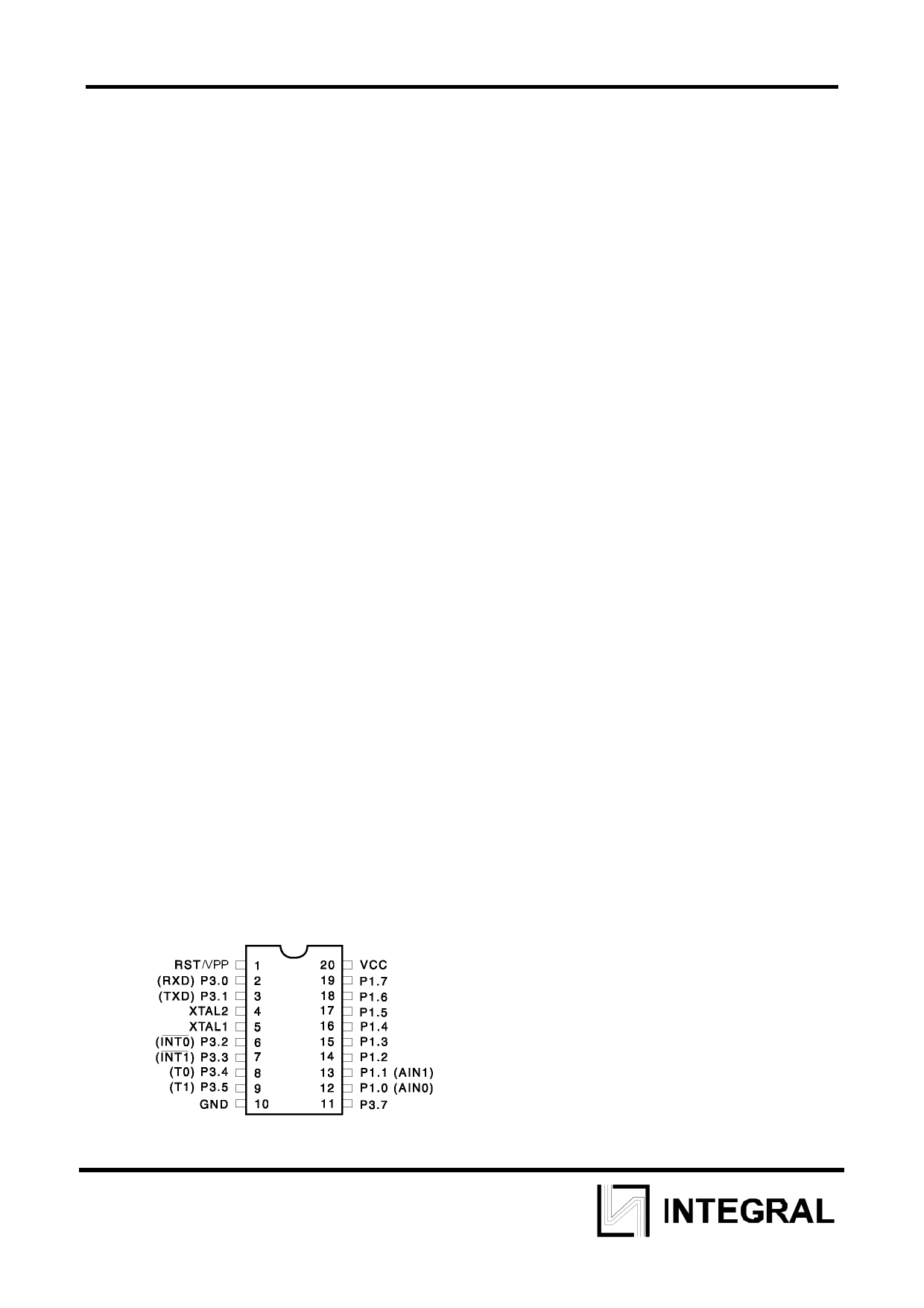
Pin Configuration
1
1 page 
IN89C2051
Table 1. IN89C2051 SFR Map and Reset Values
Restrictions on Certain Instructions
The IN89C2051 and is an economical and cost-effective member of Atmel’s
growing family of microcontrollers. It contains 2K bytes of flash program memory. It is fully
compatible with the MCS-51 architecture, and can be programmed using the MCS-51
instruction set. However, there are a few considerations one must keep in mind when
utilizing certain instructions to program this device. All the instructions related to jumping
or branching should be restricted such that the destination address falls within the physical
program memory space of the device, which is 2K for the IN89C2051. This should be the
responsibility of the software programmer. For example, LJMP 7E0H would be a valid
instruction for the IN89C2051 (with 2K of memory), whereas LJMP 900H would not.
1. Branching instructions:
LCALL, LJMP, ACALL, AJMP, SJMP, JMP @A+DPTR These unconditional
branching instructions will execute correctly as long as the programmer keeps in mind that
the destination branching address must fall within the physical boundaries of the program
memory size (locations 00H to 7FFH for the 89C2051). Violating the physical space limits
may cause unknown program behavior.
5
5 Page 
Absolute Maximum Ratings*
IN89C2051
Operating Temperature
Storage Temperature
Voltage on Any Pin with Respect to Ground
Maximum Operating Voltage
DC Output Current
-55°C to +125°C
-65°C to +150°C
-1.0V to +7.0V
6.6V
25.0 mA
DC Characteristics
TA = -40°C to 85°C, VCC = 2.0V to 6.0V (unless otherwise noted)
Symbol Parameter
Condition
Min Max
VIL Input Low Voltage
VIH Input High Voltage
(Except XTAL1, RST)
VIH1 Input High Voltage
(XTAL1, RST)
VOL
Output Low Voltage(1)
IOL = 20 mA, VCC = 5V
(Ports 1, 3)
IOL = 10 mA, VCC = 2.7V
-0.5 0.2 VCC - 0.1
0.2 VCC + 0.9 VCC + 0.5
0.7 VCC
VCC + 0.5
0.5
Units
V
V
V
V
VOH
IIL
ITL
ILI
VOS
VCM
RRST
CIO
ICC
Output High Voltage
(Ports 1, 3)
Logical 0 Input Current
(Ports 1, 3)
IOH = -80 µA, VCC = 5V ± 10%
IOH = -30 µA
IOH = -12 µA
VIN = 0.45V
2.4
0.75 VCC
0.9 VCC
Logical 1 to 0 Transition
Current
(Ports 1, 3)
VIN = 2V, VCC
= 5V ± 10%
Input Leakage Current
0 < VIN < VCC
(Port P1.0, P1.1)
Comparator Input Offset
Voltage
VCC = 5V
Comparator Input Common
0
Mode Voltage
Reset Pulldown Resistor
50
Pin Capacitance
Power Supply Current
Test Freq. = 1 MHz, TA = 25°C
Active Mode, 12 MHz, VCC =
6V/3V
Power Down Mode(2)
Idle Mode, 12 MHz, VCC = 6V/3V
P1.0 & P1.1 = 0V or VCC
VCC = 6V P1.0 & P1.1 = 0V or VCC
VCC = 3V P1.0 & P1.1 = 0V or VCC
-50
-750
±10
20
VCC
300
10
15/5.5
5/1
100
20
V
V
V
µA
µA
µA
mV
V
KΩ
pF
mA
mA
µA
µA
Notes: 1. Under steady state (non-transient) conditions, IOL must be externally limited as
follows: Maximum IOL per port pin: 20 mA
Maximum total IOL for all output pins: 80 mA
(If I)OL (exceeds the test condition, V)OL may exceed the related specification. Pins are
not guaranteed to sink current greater than the listed test conditions.
2. (Minimum V)CC for Power Down is 2V.
11
11 Page | ||
| Páginas | Total 13 Páginas | |
| PDF Descargar | [ Datasheet IN89C2051.PDF ] | |
Hoja de datos destacado
| Número de pieza | Descripción | Fabricantes |
| IN89C2051 | 8-BIT MICROCONTROLLER | Integral |
| IN89C2051DW | 8-BIT MICROCONTROLLER | Integral |
| Número de pieza | Descripción | Fabricantes |
| SLA6805M | High Voltage 3 phase Motor Driver IC. |
Sanken |
| SDC1742 | 12- and 14-Bit Hybrid Synchro / Resolver-to-Digital Converters. |
Analog Devices |
|
DataSheet.es es una pagina web que funciona como un repositorio de manuales o hoja de datos de muchos de los productos más populares, |
| DataSheet.es | 2020 | Privacy Policy | Contacto | Buscar |