|
|
|
PDF ISL78322 Data sheet ( Hoja de datos )
| Número de pieza | ISL78322 | |
| Descripción | Dual 2A/1.7A Low Quiescent Current 2.25MHz High Efficiency Synchronous Buck Regulator | |
| Fabricantes | Intersil | |
| Logotipo | ||
Hay una vista previa y un enlace de descarga de ISL78322 (archivo pdf) en la parte inferior de esta página. Total 18 Páginas | ||
|
No Preview Available !
DATASHEET
Dual 2A/1.7A Low Quiescent Current 2.25MHz High
Efficiency Synchronous Buck Regulator
ISL78322
The ISL78322 is a high efficiency, dual synchronous step-down
DC/DC regulator that can deliver up to 2A/1.7A continuous
output current per channel. The channels are 180° out-of-phase
for input RMS current and EMI reduction. The supply voltage
range of 2.8V to 5.5V allows for the use of a single Li+ cell, three
NiMH cells or a regulated 5V input. The current mode control
architecture enables very low duty cycle operation at high
frequency with fast transient response and excellent loop
stability. The ISL78322 operates at 2.25MHz switching frequency
which allows for the use of small, low cost inductors and
capacitors. Each channel is optimized for generating an output
voltage as low as 0.6V.
The ISL78322 has a user configurable mode of operation-forced
PWM mode and PFM/PWM mode. The forced PWM mode
reduces noise and RF interference while the PFM mode provides
highest efficiency by reducing switching losses at light loads. In
PFM mode of operation, both channels draw a total quiescent
current of only 40µA, hence enabling high light load efficiency
and maximizing battery life.
The ISL78322 offers a 1ms Power-Good (PG) signal to monitor
both outputs at power-up. When shut down, ISL78322
discharges the output capacitors. Other features include internal
digital soft-start, enable for power sequence, overcurrent
protection, and thermal shutdown. The ISL78322 is offered in a
4mmx3mm, 12 Lead DFN package with 1mm maximum height.
The complete converter occupies less than 1.8cm2 area.
The ISL78322 is qualified to AEC-Q100 and specified for
operation across the -40°C to +105°C (grade 2) ambient
temperature range.
Features
• Dual 2A/1.7A high efficiency synchronous buck regulator with
up to 97% efficiency, low IQ (40µA)
• 180° out-of-phase outputs reduce ripple current and EMI
• Start-up with prebiased output prevents negative current flow
in output stage
• Selectable forced PWM mode and PFM mode
• External synchronization up to 8MHz
• Negative current detection and protection
• 100% maximum duty cycle for lowest dropout
• Internal current mode compensation
• Peak current limiting, hiccup mode short circuit protection and
over-temperature protection
• Pb-free (RoHs compliant)
• AEC-Q100 qualified component
Applications
• DC/DC POL modules
• µC/µP, FPGA and DSP power
• Automotive embedded processor power supply systems
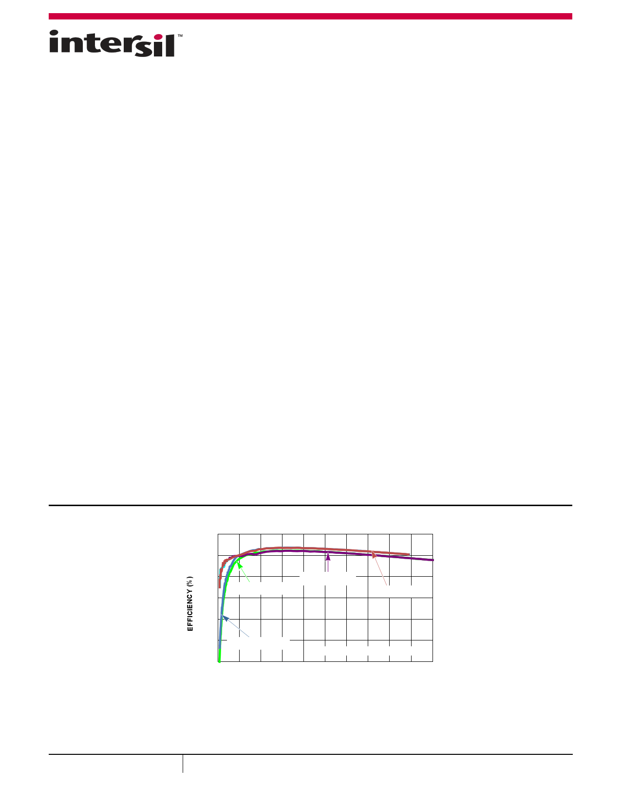
100
90
80 2.5VOUT1 PFM
2.5VOUT1 PWM
70
3.3VOUT2 PFM
60
50 3.3VOUT2 PWM
2.25MHz 5VIN AT +25°C
400.0 0.2 0.4 0.6 0.8 1.0 1.2 1.4 1.6 1.8
OUTPUT LOAD (A)
2.0
FIGURE 1. CHARACTERISTIC CURVE
August 26, 2014
FN7908.2
1
CAUTION: These devices are sensitive to electrostatic discharge; follow proper IC Handling Procedures.
1-888-INTERSIL or 1-888-468-3774 | Copyright Intersil Americas LLC 2012, 2014. All Rights Reserved
Intersil (and design) is a trademark owned by Intersil Corporation or one of its subsidiaries.
All other trademarks mentioned are the property of their respective owners.
1 page 
ISL78322
Absolute Maximum Ratings (Reference to GND)
Supply Voltage (VIN) . . . . . . . . . . . . . . . . . . . . -0.3V to 6V (DC) or 7V (20ms)
EN1, EN2, PG, SYNC . . . . . . . . . . . . . . . . . . . . . . . . . . . . . .-0.3V to VIN + 0.3V
LX1, LX2. . . . . . . . . . . . . . . . . . . . . . . -1.5V (100ns)/-0.3V (DC) to 6.5V (DC)
. . . . . . . . . . . . . . . . . . . . . . . . . . . . . . . . . . . . . . . . . . . . . . . . . . . or 7V (20ms)
FB1, FB2 . . . . . . . . . . . . . . . . . . . . . . . . . . . . . . . . . . . . . . . . . . . -0.3V to 2.7V
ESD Rating
Human Body Model (Tested per JESD22-A114F) . . . . . . . . . . . . . . . . 3kV
Machine Model(Tested per JESD22-C101E) . . . . . . . . . . . . . . . . . . 250V
Charged Device Model (Tested per AEC-Q100-11) . . . . . . . . . . . . . . . 2kV
Latch-up (Tested per JESD-78B; Class 2, Level A) . . . . . . . . . . . . . . 100mA
Thermal Information
Thermal Resistance (Typical)
JA (°C/W) JC (°C/W)
4x3 DFN Package (Notes 4, 5) . . . . . . . .
41
3
Junction Temperature Range . . . . . . . . . . . . . . . . . . . . . . .-55°C to +150°C
Storage Temperature Range. . . . . . . . . . . . . . . . . . . . . . . .-65°C to +150°C
Pb-Free Reflow Profile . . . . . . . . . . . . . . . . . . . . . . . . . . . . . . . . . . see TB493
Recommended Operating Conditions
VIN Supply Voltage Range . . . . . . . . . . . . . . . . . . . . . . . . . . . . . . 2.8V to 5.5V
Load Current Range Channel 1 . . . . . . . . . . . . . . . . . . . . . . . . . . . . 0A to 2A
Load Current Range Channel 2 . . . . . . . . . . . . . . . . . . . . . . . . . . 0A to 1.7A
Ambient Temperature Range . . . . . . . . . . . . . . . . . . . . . . .-40°C to +105°C
CAUTION: Do not operate at or near the maximum ratings listed for extended periods of time. Exposure to such conditions may adversely impact product
reliability and result in failures not covered by warranty.
NOTES:
4. JA is measured in free air with the component mounted on a high effective thermal conductivity test board with “direct attach” features. See Tech
Brief TB379.
5. JC, “case temperature” location is at the center of the exposed metal pad on the package underside.
Electrical Specifications Unless otherwise noted, all parameter limits are established over the recommended operating
conditions: TA = -40°C to +105°C, VIN = 2.8V to 5.5V, EN1 = EN2 = VIN, SYNC = 0V, L = 1.2µH, C1 = 2 x 10µF, C2 = C4 = 22µF, IOUT1 = 0A to 2A,
IOUT2 = 0A to 1.7A. (Typical values are at TA = +25°C, VIN = 3.6V). Boldface limits apply across the operating temperature range,
-40°C to +105°C.
PARAMETER
SYMBOL
TEST CONDITIONS
MIN MAX
(Note 6) TYP (Note 6)
UNITS
INPUT SUPPLY
VIN Undervoltage Lock-out Threshold
VUVLO
Rising
Falling
2.5 2.8
2.0 2.4
V
V
Quiescent Supply Current
IVIN SYNC = VIN, EN1 = EN2 = VIN, no switches
switching
40 55
µA
Shutdown Supply Current
OUTPUT REGULATION
SYNC = GND, EN1 = EN2 = VIN,
fSW = 2.25MHz, no load at the output
ISD VIN = 5.5V, EN1 = EN2 = GND
0.86
6.5
1
12
mA
µA
FB1, FB2 Regulation Voltage
FB1, FB2 Bias Current
Output Voltage Accuracy
VFB_
IFB_
VFB = 0.55V
SYNC = VIN, Io = 0A to 2A
SYNC = GND, Io = 0A to 2A
0.590
0.6
0.1
±1.5
±1
0.610
V
µA
%
%
Line Regulation
Soft-Start Ramp Time Cycle
VIN = VO + 0.5V to 5.5V (minimal 2.8V)
0.2 %/V
1.3 ms
OVERCURRENT PROTECTION
Dynamic Current Limit ON-time
tOCON
17 Clock
pulses
Dynamic Current Limit OFF-time
Peak Overcurrent Limit
Peak SKIP Limit
tOCOFF
Ipk1
Ipk2
Iskip1
Iskip2
4 SS cycle
2.7 3.2 3.6
A
2.3 2.8 3.2
A
520 610 730
mA
520 610 730
mA
Submit Document Feedback
5
FN7908.2
August 26, 2014
5 Page 
ISL78322
Typical Operating Performance (Unless otherwise noted) operating conditions are:
TA = +25°C, VVIN = 2.8V to 5.5V, EN = VIN, L1 = L2 = 1.2µH, C1 = 10µF, C2 = C4 = 22µF, IOUT1 = 0A to 2A, IOUT2 = 0A to 1.7A. (Continued)
EN1 2V/DIV
VOUT1 1V/DIV
IL1 0.5A/DIV
PG 5V/DIV
TB = 500µs/DIV
FIGURE 26. SOFT-START AT NO LOAD CHANNEL 1 (PFM)
EN2 2V/DIV
VOUT2 1V/DIV
IL2 0.5A/DIV
PG 5V/DIV
TB = 500µs/DIV
FIGURE 27. SOFT-START AT NO LOAD CHANNEL 2 (PFM)
EN1 2V/DIV
VOUT1 1V/DIV
IL1 1A/DIV
PG 5V/DIV
TB = 500µs/DIV
FIGURE 28. SOFT-START AT FULL LOAD CHANNEL 1
EN1 2V/DIV
VOUT1 1V/DIV
IL1 0.2A/DIV
PG 5V/DIV
TB = 200µs/DIV
FIGURE 30. SOFT-DISCHARGE SHUTDOWN CHANNEL 1
EN2 2V/DIV
VOUT2 1V/DIV
IL2 1A/DIV
PG 5V/DIV
TB = 500µs/DIV
FIGURE 29. SOFT-START AT FULL LOAD CHANNEL 2
EN2 2V/DIV
VOUT2 1V/DIV
IL2 0.2A/DIV
PG 5V/DIV
TB = 200µs/DIV
FIGURE 31. SOFT-DISCHARGE SHUTDOWN CHANNEL 2
Submit Document Feedback 11
FN7908.2
August 26, 2014
11 Page | ||
| Páginas | Total 18 Páginas | |
| PDF Descargar | [ Datasheet ISL78322.PDF ] | |
Hoja de datos destacado
| Número de pieza | Descripción | Fabricantes |
| ISL78322 | Dual 2A/1.7A Low Quiescent Current 2.25MHz High Efficiency Synchronous Buck Regulator | Intersil |
| Número de pieza | Descripción | Fabricantes |
| SLA6805M | High Voltage 3 phase Motor Driver IC. |
Sanken |
| SDC1742 | 12- and 14-Bit Hybrid Synchro / Resolver-to-Digital Converters. |
Analog Devices |
|
DataSheet.es es una pagina web que funciona como un repositorio de manuales o hoja de datos de muchos de los productos más populares, |
| DataSheet.es | 2020 | Privacy Policy | Contacto | Buscar |