|
|
|
PDF ISL23328 Data sheet ( Hoja de datos )
| Número de pieza | ISL23328 | |
| Descripción | Low Voltage Digitally Controlled Potentiometer | |
| Fabricantes | Intersil | |
| Logotipo | ||
Hay una vista previa y un enlace de descarga de ISL23328 (archivo pdf) en la parte inferior de esta página. Total 20 Páginas | ||
|
No Preview Available !
Dual, 128-Tap, Low Voltage Digitally Controlled
Potentiometer (XDCP™)
ISL23328
The ISL23328 is a volatile, low voltage, low noise, low power,
128-Tap, dual digitally controlled potentiometer (DCP) with an
I2C Bus™ interface. It integrates two DCP cores, wiper switches
and control logic on a monolithic CMOS integrated circuit.
Each digitally controlled potentiometer is implemented with a
combination of resistor elements and CMOS switches. The
position of the wipers are controlled by the user through the I2C
bus interface. Each potentiometer has an associated volatile
Wiper Register (WRi, i = 0, 1) that can be directly written to and
read by the user. The contents of the WRi controls the position
of the wiper. When powered on, the wiper of each DCP will
always commence at mid-scale (64 tap position).
The low voltage, low power consumption, and small package
of the ISL23328 make it an ideal choice for use in battery
operated equipment. In addition, the ISL23328 has a VLOGIC
pin allowing down to 1.2V bus operation, independent from the
VCC value. This allows for low logic levels to be connected
directly to the ISL23328 without passing through a voltage
level shifter.
The DCP can be used as a three-terminal potentiometer or as a
two-terminal variable resistor in a wide variety of applications
including control, parameter adjustments, and signal
processing.
Applications
• Power supply margining
• Trimming sensor circuits
• Gain adjustment in battery powered instruments
• RF power amplifier bias compensation
Features
• Two potentiometers per package
• 128 resistor taps
• 10kΩ, 50kΩ or 100kΩ total resistance
• I2C serial interface
- No additional level translator for low bus supply
- Three address pins allow up to eight devices per bus
• Power supply
- VCC = 1.7V to 5.5V analog power supply
- VLOGIC = 1.2V to 5.5V I2C bus/logic power supply
• Maximum supply current without serial bus activity
(standby)
- 3µA @ VCC and VLOGIC = 5V
- 1.7µA @ VCC and VLOGIC = 1.7V
• Shutdown Mode
- Forces the DCP into an end-to-end open circuit and RWi is
connected to RLi internally
- Reduces power consumption by disconnecting the DCP
resistor from the circuit
• Wiper resistance: 70Ω typical @ VCC = 3.3V
• Power-on preset to mid-scale (64 tap position)
• Extended industrial temperature range: -40°C to +125°C
• 14 Ld TSSOP or 16 Ld UTQFN packages
• Pb-free (RoHS Compliant)
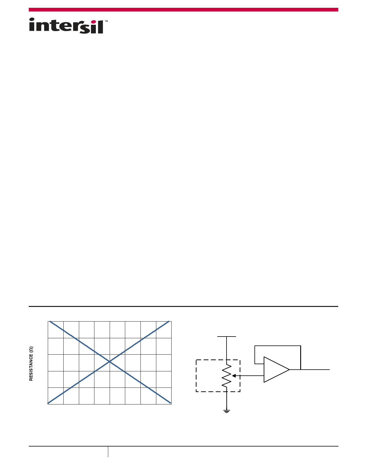
10000
8000
6000
4000
2000
0
0 32 64 96 128
TAP POSITION (DECIMAL)
FIGURE 1. FORWARD AND BACKWARD RESISTANCE vs TAP
POSITION, 10kΩ DCP
VREF
RH1
1 DCP
OF
ISL23328
RW1
RL1
-
+
ISL28114
VREF_M
FIGURE 2. VREF ADJUSTMENT
September 29, 2015
FN7902.1
1
CAUTION: These devices are sensitive to electrostatic discharge; follow proper IC Handling Procedures.
1-888-INTERSIL or 1-888-468-3774 | Copyright Intersil Americas LLC 2011, 2015. All Rights Reserved
Intersil (and design) and XDCP are trademarks owned by Intersil Corporation or one of its subsidiaries.
All other trademarks mentioned are the property of their respective owners.
1 page 
ISL23328
Analog Specifications VCC = 2.7V to 5.5V, VLOGIC = 1.2V to 5.5V over recommended operating conditions unless otherwise stated.
Boldface limits apply over the operating temperature range, -40°C to +125°C. (Continued)
SYMBOL
PARAMETER
TEST CONDITIONS
MIN
(Note 19)
TYP
(Note 7)
MAX
(Note 19)
UNITS
VOLTAGE DIVIDER MODE (0V @ RL; VCC @ RH; measured at RW, unloaded)
INL Integral Non-linearity, Guaranteed
(Note 12) Monotonic
W option
-0.5
±0.15
+0.5
LSB
(Note 8)
U, T option
-0.5
±0.15
+0.5
LSB
(Note 8)
DNL Differential Non-linearity, Guaranteed W option
(Note 11) Monotonic
-0.5
±0.15
+0.5
LSB
(Note 8)
U, T option
-0.5
±0.15
+0.5
LSB
(Note 8)
FSerror Full-scale Error
W option
-3 -1.5 0 LSB
(Note 8)
U, T option
-1.5 -0.9
0 LSB
(Note 8)
ZSerror Zero-scale Error
(Note 9)
W option
0 1.5 3 LSB
(Note 8)
U, T option
0 0.9 1.5 LSB
(Note 8)
Vmatch DCP to DCP Matching
(Note 21)
DCPs at same tap position, same
voltage at all RH terminals, and same
voltage at all RL terminals
-2
±0.5
2 LSB
(Note 8)
TCV Ratiometric Temperature Coefficient W option, Wiper Register set to 40 hex 8 ppm/°C
(Notes 13)
U option, Wiper Register set to 40 hex
4 ppm/°C
T option, Wiper Register set to 40 hex
2.3 ppm/°C
tLS_Settling Large Signal Wiper Settling Time
From code 0 to 7F hex, measured from
0 to 1 LSB settling of the wiper
300
ns
fcutoff -3dB Cutoff Frequency
Wiper at middle point W option
Wiper at middle point U option
1200
250
kHz
kHz
Wiper at middle point T option
120 kHz
RHEOSTAT MODE (Measurements between RW and RL pins with RH not connected, or between RW and RH with RL not connected)
RINL Integral Non-linearity, Guaranteed
(Note 17) Monotonic
W option; VCC = 2.7V to 5.5V
-1.0
±0.5
+1.0
MI
(Note 14)
W option; VCC = 1.7V
4 MI
(Note 14)
U, T option; VCC = 2.7V to 5.5V
-0.5
±0.15
+0.5
MI
(Note 14)
U, T option; VCC = 1.7V
1 MI
(Note 14)
RDNL Differential Non-linearity, Guaranteed W option; VCC = 2.7V to 5.5V
(Note 16) Monotonic
-0.5
±0.15
+0.5
MI
(Note 14)
W option; VCC = 1.7V
±0.4
MI
(Note 14)
U, T option; VCC = 2.7V to 5.5V
-0.5
±0.15
+0.5
MI
(Note 14)
U, T option; VCC = 1.7V
±0.4
MI
(Note 14)
5 FN7902.1
September 29, 2015
5 Page 
ISL23328
Typical Performance Curves (Continued)
0.30
0.08
0.15
0.04
0.00
0.00
-0.15
-0.04
-0.30
0
32 64 96
TAP POSITION (DECIMAL)
128
FIGURE 9. 10kΩ RINL vs TAP POSITION, VCC = 3.3V, +25°C
-0.08 0
32 64 96
TAP POSITION (DECIMAL)
128
FIGURE 10. 50kΩ RINL vs TAP POSITION, VCC = 3.3V, +25°C
100
+125°C
80 +25°C
60
40 -40°C
20
120
100
+25°C
+125°C
80
60
-40°C
40
20
0
0 32 64 96 128
TAP POSITION (DECIMAL)
FIGURE 11. 10kΩ WIPER RESISTANCE vs TAP POSITION, VCC = 3.3V
0
0 32 64 96 128
TAP POSITION (DECIMAL)
FIGURE 12. 50kΩ WIPER RESISTANCE vs TAP POSITION, VCC = 3.3V
200
150
100
50
0
15 43 71 99
TAP POSITION (DECIMAL)
FIGURE 13. 10kΩ TCv vs TAP POSITION, VCC = 3.3V
127
11
40
30
20
10
0
15 43 71 99
TAP POSITION (DECIMAL)
FIGURE 14. 50kΩ TCv vs TAP POSITION, VCC = 3.3V
127
FN7902.1
September 29, 2015
11 Page | ||
| Páginas | Total 20 Páginas | |
| PDF Descargar | [ Datasheet ISL23328.PDF ] | |
Hoja de datos destacado
| Número de pieza | Descripción | Fabricantes |
| ISL23325 | Low Voltage Digitally Controlled Potentiometer | Intersil |
| ISL23328 | Low Voltage Digitally Controlled Potentiometer | Intersil |
| Número de pieza | Descripción | Fabricantes |
| SLA6805M | High Voltage 3 phase Motor Driver IC. |
Sanken |
| SDC1742 | 12- and 14-Bit Hybrid Synchro / Resolver-to-Digital Converters. |
Analog Devices |
|
DataSheet.es es una pagina web que funciona como un repositorio de manuales o hoja de datos de muchos de los productos más populares, |
| DataSheet.es | 2020 | Privacy Policy | Contacto | Buscar |