|
|
|
PDF AME5285 Data sheet ( Hoja de datos )
| Número de pieza | AME5285 | |
| Descripción | Rectified Step-Down Converter | |
| Fabricantes | AME | |
| Logotipo | ||
Hay una vista previa y un enlace de descarga de AME5285 (archivo pdf) en la parte inferior de esta página. Total 16 Páginas | ||
|
No Preview Available !
AME
AME5285
5A, 300KHz ~ 1.4MHz Synchronous
Rectified Step-Down Converter
n General Description
The AME5285 is a Synchronous Rectified Step-Down
Converter with internal power MOSFETs. It achieves 5A
continous output current over a wide switching frequency
range with excellent load and line regulation.
Current mode operation provides fast transient response
and eases of loop stabilization. Internal soft-start mini-
mizes the inrush supply current at startup. The circuit
protection includes cycle-by cycle current limiting, out-
put short circuit frequency protection and thermal shut-
down.
This device is available in SOP-8/PP package with ex-
posed pad for low thermal resistance.
n Features
l 5A Output Current
l 55mΩ/45mΩ Internal Power MOSFET Switch
l Stable with Low ESR Output Ceramic Capacit
-ors
l Up to 95% Efficiency
l Less than 10µA Shutdown Current
l Wide Switching Frequency Range from
300KHz~1.4MHz
l Thermal Shutdown
l Cycle by cycle Over Current Protection and
Hiccup
l Output Adjustable from 0.8V to VIN
l Short Circuit Frequency Protection
l Green Products Meet RoHS Standards
n Applications
l TV
l Distributed Power Systems
l Pre-Regulator for Linear Regulators
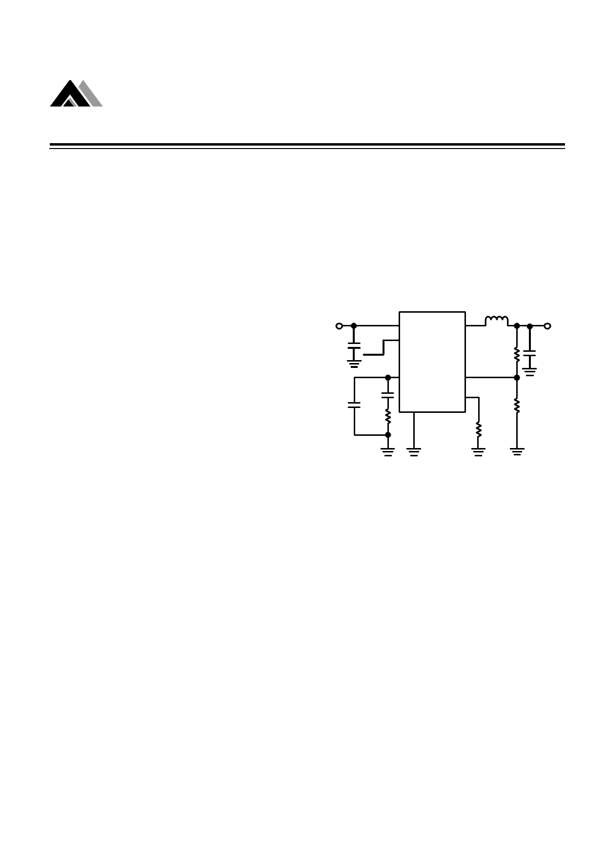
n Typical Application
VIN
5V
CIN
10µF
IN SW
EN
OFF ON AME5285
C2
Optional
C1
680pF
R3
5.1K
COMP
FB
GND FREQ
RFREQ
30K
L1
1.5µH
R1
6K
R2
24K
VOUT
1V 5A
COUT
22µF
Rev. B.01
1
1 page 
AME
AME5285
5A, 300KHz ~ 1.4MHz Synchronous
Rectified Step-Down Converter
n Absolute Maximum Ratings
Parameter
Supply Voltage
Switch voltage
EN, FB, COMP, FREQ to GND
ESD Classification
HBM
MM
Maximum
-0.3V to +6V
-0.7V to VIN+0.7V
-0.3V to VIN+0.3V
2
200
Unit
V
V
V
kV
V
n Recommended Operating Conditions
Parameter
Ambient Temperature Range
Junction Temperature Range
Storage Temperature Range
Symbol
TA
TJ
T STG
Rating
-40 to +85
-40 to +125
-65 to +150
Unit
oC
n Thermal Information
Parameter
Package Die Attach Symbol Maximum Unit
Thermal Resistance*
(Junction to Case)
Thermal Resistance
(Junction to Ambient)
SOP-8/PP Conductive Epoxy
Internal Power Dissipation
Maximum Junction Temperature
Lead Temperature (Soldering 10Sec)**
θJC
θJA
PD
15
75
1.333
150
260
oC / W
mW
oC
oC
* Measure θJC on backside center of Exposed Pad.
** MIL-STD-202G 210F
Rev. B.01
5
5 Page 
AME
AME5285
n Typical Operating Circuit
5A, 300KHz ~ 1.4MHz Synchronous
Rectified Step-Down Converter
VIN
3V to 5V
CIN
10µF
Chip Enable
C2
Optional
C1
R3
1
IN
3 EN
SW 5 , 6
L
R1
AME5285
48
COMP
FB
7
FREQ
2
GND
GND 9 (Exposed pad)
RFREQ
R2
VOUT
COUT
V OUT(V)
3.3
2.5
1.8
1.5
1.2
1.1
CIN(µF)
10
10
10
10
10
10
R1(KΩ
75
51
30
21
12
6
R2(KΩ
24
24
24
24
24
24
R3(KΩ
25
20
15
13
11
8.2
C1 pF
680
680
680
680
680
680
L(µH)
2.2
2.2
1.5
1.5
1.5
1.5
Table 1. Recommended Components Selectin for fsw = 1.4MHz
COUT µF
22
22
22
22
22
22
Rev. B.01
R3
The ground area must provide adequate heat
dissipating area to the thermal pad andusing
Connect the
C1
multiple vias to help thermal dissipation.
FB pin directly
to feedback
R2 resistors.
COMP 1
8 FB
VOUT
R1
GND 2
GND
7 FREQ
GND
RFREQ
EN 3
VIN
VIN
4
6 SW
SW
5 SW
SW pad should be
connected together to
Inductor by wide and short
trace, keep sensitive
components away from
this trace.
L1
C IN must be placed
between V IN and
GND as close as CIN
possible
Place the input and output
capacitors as close to the
IC as possible
COUT VOUT
Figure 3. AME5285 Regulators Layout Diagram
11
11 Page | ||
| Páginas | Total 16 Páginas | |
| PDF Descargar | [ Datasheet AME5285.PDF ] | |
Hoja de datos destacado
| Número de pieza | Descripción | Fabricantes |
| AME5283 | Rectified Step-Down Converter | AME |
| AME5284 | Rectified Step-Down Converter | AME |
| AME5285 | Rectified Step-Down Converter | AME |
| AME5286 | Rectified Step-Down Converter | AME |
| Número de pieza | Descripción | Fabricantes |
| SLA6805M | High Voltage 3 phase Motor Driver IC. |
Sanken |
| SDC1742 | 12- and 14-Bit Hybrid Synchro / Resolver-to-Digital Converters. |
Analog Devices |
|
DataSheet.es es una pagina web que funciona como un repositorio de manuales o hoja de datos de muchos de los productos más populares, |
| DataSheet.es | 2020 | Privacy Policy | Contacto | Buscar |